Table of Contents

Related Manuals for Amazone GHD 1500


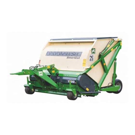
Summary of Contents for Amazone GHD 1500
- Page 1 Operating manual AMAZONE GROUNDKEEPER GHD SMARTCUT Please read and follow this op- erating manual before putting MG5072 the machine into operation. BAF0007.2 02.21 Keep it in a safe place for future Printed in France use.
- Page 2 READING THE INSTRUCTION manual and adhering to it should not appear to be inconvenient and superfluous as it is not enough to hear from others and to realise that a machine is good, to buy it and to believe that now everything should work by itself.
- Page 3 +33 (0) 3 87 84 65 71 E-mail: forbach@amazone.fr Spare part orders Spare parts lists are freely accessible in the spare parts portal at www.amazone.de. Please send orders to your AMAZONE dealer. Formalities of the operating manual Document number: MG5072 Compilation date: 02.21 ã...
- Page 4 User evaluation Dear Reader We update our operating manuals regularly. Your suggestions for improvement help us to create ever more user-friendly manuals. Please send your suggestions to: AMAZONE S.A. FORBACH 17, rue de la Verrerie BP 90106 F-57602 Forbach, France...
-
Page 5: Table Of Contents
Table of Contents User information ................... 7 Purpose of the document ....................... 7 Locations in the operating manual ..................7 Diagrams used ........................7 General safety instructions ................. 8 Obligations and liability ......................8 Representation of safety symbols ..................10 Organisational measures ..................... - Page 6 Table of Contents Fitting the mowing and scarifying tools ................. 43 Mowing ..........................49 Scarifying ..........................50 Mulching ..........................52 Collecting ..........................53 Emptying the hopper ......................53 Transport on public roads ..................... 54 Adjusting the cutting height ..............55 Front roller ..........................
-
Page 7: User Information
User information User information The "User information" section supplies information on using the op- erating manual. Purpose of the document This operating manual • Describes the operation and maintenance of the machine. • Provides important information on safe and efficient handling of the machine. -
Page 8: General Safety Instructions
General safety instructions General safety instructions This section contains important information on safe operation of the machine. Obligations and liability Comply with the instructions in the operating manual Knowledge of the basic safety information and safety regulations is a basic requirement for safe handling and fault-free machine operation. Obligations of the operator The operator is obliged only to let those people work with/on the ma- chine who... - Page 9 General safety ins Risks in handling the machine The machine has been constructed to the state-of-the art and the recognised rules of safety. However, there may be risks and re- strictions which occur when operating the machine • For the health and safety of the user or third persons, •...
-
Page 10: Representation Of Safety Symbols
General safety instructions Representation of safety symbols Safety instructions are indicated by the triangular safety symbol and the highlighted signal word. The signal word (DANGER, WARNING, CAUTION) describes the gravity of the risk and has the following sig- nificance: DANGER Indicates an immediate high risk, which will result in death or extremely serious physical injury (loss of body parts or long term damage) if not avoided. -
Page 11: Organisational Measures
General safety ins Organisational measures The operator must provide the necessary personal protective equip- ment, such as: • Protective glasses • Protective shoes • Protective suit • Skin protection, etc. The operation manual • Must always be kept at the place at which the machine is oper- ated. -
Page 12: User Training
General safety instructions User training Only those people who have been trained and instructed may work with/on the machine. The operator must clearly specify the responsi- bilities of the people charged with operation, maintenance and repair work. People being trained may only work with/on the machine under the supervision of an experienced person. -
Page 13: Safety Measures In Normal Operation
General safety ins Safety measures in normal operation Only operate the machine if all the safety and protection equipment is fully functional. Check the machine at least once a day for visible damage and check the function of the safety and protection equipment. Dangers from residual energy Note that there may be residual mechanical, hydraulic, pneumatic and electrical/electronic energy at the machine. -
Page 14: Spare And Wear Parts And Aids
General safety instructions 2.10.1 Spare and wear parts and aids Immediately replace any machine parts which are not in a perfect state. Use only genuine spare and wear parts or the parts cleared by AMAZONEN-WERKE so that the operating permit retains its validity in accordance with national and international regula- tions. -
Page 15: Warning Symbols And Other Signs On The Machine
General safety ins 2.13 Warning symbols and other signs on the machine Always keep all the warning symbols of the machine clean and in a legible state. Replace illegible warning symbols. You can obtain the warning symbols from your dealer using the order number (e.g. MD 075). - Page 16 General safety instructions Order number and explanation Warning symbols MD 075 Risk of fingers and hands being cut or sev- ered by rotating machine parts. This hazard can cause extremely serious injuries with the loss of body parts such as fingers or hands.
- Page 17 General safety ins MD 080 Danger of crushing of torso in articulated area of drawbar due to sudden steering movements! This can inflict extremely serious injuries to the torso which may also be fatal. Persons must not enter or remain in the danger zone between the tractor and machine if the tractor engine is running and the tractor is not secured to prevent it from accidentally rolling...
- Page 18 General safety instructions MD 089 Danger Risk of any part of the body being crushed in the danger area beneath suspended loads/machine parts. This hazard can cause extremely serious injuries anywhere on the body, or even death. The presence of persons under suspended loads/machine parts is prohibited.
- Page 19 General safety ins MD 096 Danger of infection to the whole body from liquids escaping at a high pressure (hydraulic fluid)! This danger will cause serious injuries over the whole body, if hydraulic fluid escaping at high pressure passes through the skin and into the body.
- Page 20 General safety instructions MD 102 Danger from unintentional machine starting and rolling during intervention in the ma- chine, e.g. installation, adjusting, trouble- shooting, cleaning, maintaining and repair- ing. This hazard can cause extremely serious injuries anywhere on the body, or even death. •...
- Page 21 General safety ins MD 115 The maximum operating pressure of the hydrau- lic system is 200 bar. MD 118 This symbol indicates the maximum drive speed (540 rpm) and direction of rotation of the drive shaft on the machine side. MD 145 The CE mark signifies that the machine complies with basic health and safety requirements.
- Page 22 General safety instructions MD 170 Risk of being crushed, drawn in or caught by unprotected, moving machine parts as a re- sult of missing safety devices. This hazard can cause extremely serious inju- ries, including the loss of body parts. Close protective equipment which has been opened or refit protective equipment which has been removed before you start the machine.
-
Page 23: Positioning Of Warning Symbols And Other Labels
General safety ins 2.13.1 Positioning of warning symbols and other labels Warning symbols The following diagrams show the arrangement of the warning symbols on the machine. MD100 MD171 MD123 MD081 MD078 MD078 MD078 MD145 MD076 MD087 MD118 MD100 MD079 MD078 MD090 MD080 MD075... -
Page 24: Dangers If The Safety Information Is Not Observed
General safety instructions 2.14 Dangers if the safety information is not observed Non-observance of the safety information • Can pose both a danger to people and also to the environment and machine. • Can lead to the loss of all warranty claims. Seen individually, non-compliance with the safety information could pose the following risks: •... -
Page 25: Safety Information For Users
General safety ins 2.16 Safety information for users WARNING Risk of being crushed, cut, caught, drawn in or struck due to insufficient traffic and operational safety! Before starting up the machine and the tractor, always check their traffic and operational safety. 2.16.1 General safety and accident prevention information •... - Page 26 General safety instructions • Be particularly careful when coupling the machine to the tractor or uncoupling it from the tractor! There are nip and shear points in the area of the coupling point between the tractor and the ma- chine. •...
- Page 27 General safety ins Machine transportation • When using public highways, national road traffic regulations must be observed. • Before moving off, check: the correct connection of the supply lines the lighting system for damage, function and cleanliness • Ensure that the tractor has sufficient steering and braking power. Any machines and front/rear weights connected to the tractor in- fluence the driving behaviour and the steering and braking power of the tractor.
-
Page 28: Hydraulic System
General safety instructions 2.16.2 Hydraulic system • The hydraulic system is under a high pressure. • Ensure that the hydraulic hose lines are connected correctly. • When connecting the hydraulic hose lines, ensure that the hy- draulic system is unpressurised on both the machine and tractor sides. -
Page 29: Electrical System
General safety ins 2.16.3 Electrical system • When working on the electrical system, always disconnect the battery (negative terminal). • Only use the prescribed fuses. If fuses are used with too high a rating, the electrical system will be destroyed – danger of fire. •... -
Page 30: General Description Of The Machine
General description of the ma General description of the machine Areas of application The AMAZONE Lift Groundkeeper with drawbar is intended to be used for grass cutting and scarifying in public parks as well as sports fields and gardens, etc. -
Page 31: Technical Data
Hopper Permissible Dimensions Model Working width Tare weight capacity total weight L x B x H [m] GHD 1500 1,50 m 1800 l 900 kg 1350 kg 3,30 x 1,90 x 1,58 GHD 1800 1,80 m 2200 l 950 kg... -
Page 32: Intended Use
Intended use also includes compliance with instructions specified by the manufacturer concerning operation, servicing and maintenance as well as the exclusive use of genuine AMAZONE spare parts. The AMAZONE Groundkeeper may only be used, serviced and main- tained by persons who are familiar with the machine and who have received instruction concerning the risks involved. -
Page 33: Taking Delivery Of The Machine
Taking delivery of Taking delivery of the machine On receiving the machine, check to see if it was damaged during transport or if parts are missing. Replacements will only be made if claims are submitted promptly to the haulage company. Please check that all the parts listed on the despatch note have been delivered. -
Page 34: Attaching And Detaching The Machine To/From The Tractor
Attaching and detaching the m Attaching and detaching the machine to/from the tractor 5.1.1 Coupling and uncoupling the machine The machine does not have a parking brake. Before uncoupling, the machine must always be secured with 2 wheel chocks, i.e. with one wheel chock under each rear wheel on both sides of the machine. -
Page 35: Hydraulic Connections
Attaching and deta 5.1.2 Hydraulic connections The maximum permissible hydraulic operating pressure is 200 bar. The hydraulic system operates under high pressure. When connecting the hydraulic hoses to the tractor's hydraulic system, care must be taken to ensure that the hydraulic system is free of pressure, both on the tractor side and on the machine side. -
Page 36: Safety Yoke
Attaching and detaching the m 5.1.4 Safety yoke Fold the yoke forward and rest it on the drawbar. Uncoupling • Bring the tractor and machine to a stop in a straight line on a level area of ground. • Retract the hydraulic cylinder on the drawbar. The machine should be standing on all tyres and the support roller. -
Page 37: Pto Shaft
Attaching and deta The machine must only be set down on level and firm ground. Before detaching the machine, check that the coupling point is not under load. - Uncouple the drawbar. - Drive the tractor away. When driving the tractor away, there must be nobody present between tractor and machine. -
Page 38: Fitting And Adapting The Pto Shaft
Attaching and detaching the m Fitting and adapting the PTO shaft 5.4.1 Fitting the PTO shaft Before fitting, clean the gearbox input shaft on the machine and always use grease to push the PTO shaft onto the input shaft. 5.4.2 Adjusting the PTO shaft when first attached When first attached, adjust the PTO shaft to the tractor accord- ing to Fig. -
Page 39: Groundkeeper Transmission Input Speed
Attaching and deta The angle defining the maximum joint bends in a universal joint on the PTO shaft can be found in the accompanying operating manual provided by the manufacturer. This manual also contains information on fitting and mainte- nance that must be observed. To avoid damage, only connect the universal joint shaft slowly when the tractor engine is running at low revs. - Page 40 Attaching and detaching the m Connection 3: Electrical socket, 3 pin (connection: DIN 9680) required electrical power: 12 V 15 A The remote control supplied with the machine, which is held in place in the driver's cab by the holder provided, allows the machine to be operated using only two hydraulic lines and one additional electrical connection.
-
Page 41: Standard Hydraulic System
Attaching and deta 4+5- Machine in float position when both switches are operated simultaneously Float position means that the mower takes control of ground tracking, with the rear wheels only providing a support function while for the most part equalising differences in ground level between the right and left-hand side wheels. - Page 42 Attaching and detaching the m The time it takes for the unit to lower after filling must be at least eight seconds. If fitted, adjust the lowering restrictor (see Fig. 5.6-1 and Fig. 5.6-2). Groundkeeper GHD SMARTCUT BAF0007.2 02.21...
-
Page 43: The Mower Unit
The mower unit The mower unit The Groundkeeper has a flail-type mower unit. This involves free- moving cutting tools which are suspended on a large-diameter tube. When the rotor starts to turn, the cutting and scarifying blades are erected by centrifugal force, which allows them to reach into the grass which is to be cut and mow it off. - Page 44 The mower unit 50 % 100 % 100 % 50 % 100 % 100 % Mowing Scarifying Scarifying Wing blade, Wing blade, Wing blade, blade blade blade long, H77 long, H77 long, H60 ground ground ground (2 mm) (3 mm) sharpened Piece Piece...
- Page 45 The mower unit used CAUTION The blades and the blade fasteners must be checked before the start of every run. All screw unions must be firmly tightened. Groundkeeper GHD SMARTCUT BAF0007.2 02.21...
- Page 46 The mower unit Blade overview Blade replacement 100% 50% Cutting 100% 100% blades Wing Wing without tools Cutting blade cutting blades cutting blades 50% Wing long H77 extralong H88 cutting blades long H77 Flower residue and envi- Dry conditions ronmental sites (bio- topes, annual moving, Wet conditions fallow land)
- Page 47 The mower unit 100% 100% 100% 100% Scarifying blade Cutting blades Cutting blades and Wing cutting Wing cutting for combination* Scarifying blade and scarifying scarifying blades blade, H60 and blade long H77 blades combined* scarifying blades and scarifying combined* combined* blades 50% Wing cutting combined *...
- Page 48 The mower unit The figure shows the standard equipment with cutting blades and flail blades H77. Caution: When you intend to work on the rotor with the hopper raised, make sure that the rotor is stationary and fit the safety support on the hopper.
-
Page 49: Mowing
The mower unit Mowing The cutting tools described above are used for mowing or scarifying. The working speed depends on the density and wetness of the turf. It must be adjusted to suit the conditions. The maximum PTO shaft speed of 540 rpm must be observed. The hopper must be emptied in good time to ensure tidy collection. -
Page 50: Scarifying
The mower unit Scarifying Scarifying is usually carried out at the start or end of vegetation growth. It is possible to clean and aerate turf containing thatch and moss by simultaneously mowing, scarifying and collecting in one operation. To achieve this, straight scarifying blades are fitted between the pairs of curved mowing blades. - Page 51 The mower unit GH 1800 • Narrow scarifying, blade spacing 17 mm Scarifying blades must be attached to all clip bolts on the rotor. This type of scarifying is relatively aggressive and is suitable for restorative work on heavily thatched turf (moss) in the spring. CAUTION 1.
-
Page 52: Mulching
The mower unit Mulching If the mowing material is only to be cut off, chopped to smaller pieces and deposited back on the ground, the flap which is normally used to guard the rotor when the hopper is raised can also remain closed during mowing. -
Page 53: Collecting
The mower unit Collecting Because of the strong suction effect produced by the rotor, the ma- chine can also be used for collecting material which has already been mowed or any other material lying loose on the ground. The material is then lifted up by air suction, chopped to smaller pieces by the rotat- ing blades and conveyed through the chute to the hopper. -
Page 54: Transport On Public Roads
The mower unit Transport on public roads When travelling on the road, the machine must be raised to the re- quired height using the rear guide wheels' hydraulic system and the drawbar. The machine must always be in a level position (Fig. 6.7-1). The weight of the machine (especially if the hopper is full) should not be underestimated, particularly on tractors with a low kerb weight. -
Page 55: Adjusting The Cutting Height
Adjusting the cutting height Adjusting the cutting height The height of the guide wheels is adjusted by removing and reposi- tioning the distance sleeves (Fig. 7-1). To adjust the wheels, it is nec- essary to raise the machine using the drawbar. The guide wheel re- tractor must be removed and the sleeves positioned according to the required working height. - Page 56 Adjusting the cutting height • Move the cage roller into the required position by turning the adjusting screws (Fig. 7-3). • Tighten the clamping screws. Care must be taken to ensure that the cage roller is equally adjusted on both sides. For this purpose, a check scale has been fitted (Fig. 7- Groundkeeper GHD SMARTCUT BAF0007.2 02.21...
-
Page 57: Front Roller
Adjusting the cutting height Front roller A front roller is available as a special accessory for scarifying on une- ven terrain. It is fitted into the holders of the front guide wheels (Fig. 7.1-1). To adjust the height, the machine must first be raised and the lynch pin and the pin must be removed on both sides and the roller must be pegged in the required position Then re-secure the pin with the lynch pin. -
Page 58: Cleaning The Machine
Cleaning the machine Cleaning the machine The machine can, on occasion, become heavily soiled, especially when mowing and scarifying wet grass which is also sometimes inter- spersed with earth. In such cases, it is recommended to clean the rotor and the hopper intensively with a jet of water. Groundkeeper GHD SMARTCUT BAF0007.2 02.21... -
Page 59: Maintenance
Maintenance Maintenance The Groundkeeper was designed to be largely maintenance free. The following points, however, should be observed and receive attention. Oil level in the angular gearbox The angular gearbox on the machine does not require lubrication servicing. However, the oil level should be checked annually. The inspection screw on the side of the gearbox must be opened (Fig. - Page 60 Maintenance Groundkeeper GHD SMARTCUT BAF0007.2 02.21...
- Page 61 Maintenance Groundkeeper GHD SMARTCUT BAF0007.2 02.21...
-
Page 62: Extended Periods Of Downtime
Maintenance Extended periods of downtime If the machine is not to be used for a prolonged period, it is recom- mended that, before storing, it should be cleaned and protected using a suitable preservative product. Before re-commissioning, an author- ised garage should check that the overload clutch between the angu- lar gearbox and the belt drive is operating correctly. - Page 63 Maintenance NOTES ................................................................................................................................................................................................................................................................................................................................................................................................................................................................................................................................................................................................................................................................................................................................................................................................................................................................................................................................................................................................................................................................................................................................................................................................................ Groundkeeper GHD SMARTCUT BAF0007.2 02.21...
- Page 64 Fax: +49 5405 501-234 Germany e-mail: amazone@amazone.de http:// www.amazone.de AMAZONE S.A. FORBACH 17, rue de la Verrerie – BP 90106 Tel.: + 33 (0)3 87 84 65 70 F-57602 FORBACH Cedex Telefax: + 33 (0)3 87 84 65 71 France e-mail: forbach@amazone.fr...
Need help?
Do you have a question about the GHD 1500 and is the answer not in the manual?
Questions and answers