
Related Manuals for Igema LG40-CS


Summary of Contents for Igema LG40-CS
- Page 1 Reflex level gauge LG40-CS Version: 01/2024 D-02-B-51105-EN-02 Installation and operating instructions (English translation)
-
Page 2: Table Of Contents
Table of Contents About this document Introduction __________________________________________________ 1 Product identification and nameplate _______________________________ 2 Related documents ____________________________________________ 2 Marking of safety and warning information __________________________ 3 Copyright ____________________________________________________ 3 Safety Instructions Requirements for personnel ______________________________________ 4 Safety at work ________________________________________________ 4 Intended use of the gauge _______________________________________ 6 Damage to the product _________________________________________ 6 Contents of the packaging... - Page 3 Commissioning Before commissioning _________________________________________ 16 Commissioning at the same time as the boiler_______________________ 17 Commissioning under pressure and temperature loads ________________ 17 Servicing Preventive maintenance _______________________________________ 19 Cleaning the gauge / depressurising ______________________________ 20 Blowing through the gauge for further cleaning ______________________ 21 Cleaning the glasses __________________________________________ 21 Glass replacement ____________________________________________ 22 Case of damage...
-
Page 5: About This Document
1 About this document 1.1 Introduction The Installation and operating instructions is part of the Reflex level gauge LG40-CS. It must be made available to the responsible departments "Incoming goods, transport, assembly, commissioning and maintenance". The Installation and operating instructions must be stored in such a way that the specialist personnel has access to them at all times. -
Page 6: Product Identification And Nameplate
On the basis of the nameplate, the operating instructions can be assigned to the corresponding gauge. The operating instructions belong to gauges of the device type LG40-CS. Additions that are entered after the designation and describe the design of the gauge do not release these operating (e.g. -
Page 7: Marking Of Safety And Warning Information
This operating manual contains texts and drawings that may not be reproduced, distributed or otherwise communicated in whole or in part without the express permission of the manufacturer. The copyright of the operating instructions remains with: Igema GmbH Antwerpener Str. 1 48163 Münster Germany Violations oblige you to pay compensation. -
Page 8: Safety Instructions
Only qualified persons who are familiar with the measurement and control systems are allowed to carry out work Igema GmbH can be commissioned for the installation and maintenance. AUTION Risk of injury due to external influences External influences can lead to injuries in the absence of protective equipment •... - Page 9 AFETY NSTRUCTIONS ARNING Risk of injury due to leaking medium Inflammatory, irritating and harmful substances can escape from the gauge and lead to skin injuries and burns. This danger is also to be expected in the case of an unpressurised cooled system.
-
Page 10: Intended Use Of The Gauge
AFETY NSTRUCTIONS AUTION Risk of injury due to unsecured work area An unsecured work area can endanger working and bystanders. • Ensure safe access. • Delimit and mark the secured working area. • Sufficiently illuminate the working area. Risk of injury due to heavy loads There is a risk of injury when handling large and/or heavy gauges. -
Page 11: Contents Of The Packaging
ONTENTS OF THE PACKAGING 3 Contents of the packaging 3.1 Included 1 LG40-CS The Reflex Level gauge will be delivered as a pre-assembled unit, unless otherwise contractually agreed: • Gauge • Upper shutoff valve • Lower shutoff valve • Drain valve 2. -
Page 12: System Description
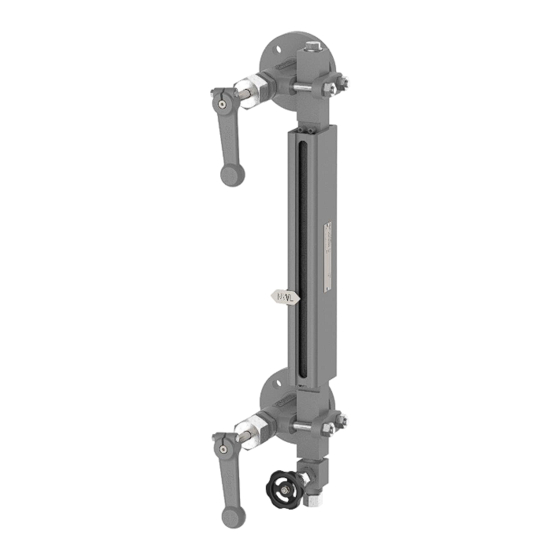
YSTEM ESCRIPTION 4 System Description 4.1 Function Reflex level gauges in different versions are used to detect the water level of steam generators or tanks. The gauge works on the principle of communicating pipes. Steam It is equipped with an elongated, flat glass, which has prismatic grooves on the medium-side surface. -
Page 13: Construction
ONSTRUCTION 5 Construction Example.: single display opening Screw plug G " Glass holder Sealing ring Screw Holders Pressure plate Clamping pins Graphite seals Drain valve Reflective glass 12.13 Shutoff valve Hexagon screws Type plate (chap. 1.2) Clamping lugs Water level mark (chap. -
Page 14: Technical Data
ECHNICAL DATA 6 Technical data 6.1 Limitations of use Application limits LG40-CS all. Pressure [PS] all. Temperature [TS] Media with glass attack 32 bar -20 to 239 °C (e.g. water vapour) 464 psig -4 to 462°F 100 bar -20 to 40 °C 1450 psig -4 to 462°F... -
Page 15: Dimensions
ECHNICAL DATA 6.3 Dimensions Single display opening Multiple display openings The displayed gauges are shown as a left-hand model. The dimensions H, J and A are to be specified individually. min. [mm] [inch] Upper blind space Lower blind space Blind space 26mm/1"... -
Page 16: Optional Versions
For versions with other shut-off and drain valves, the documents for the installed valves must also be observed. Examples of optional versions Parts in contact with media made of Inclined design stainless steel Example LG40-CS Body size 10 Example LG40-CS Inclination 20° Page / 12 D-02-B-51105-EN-02... -
Page 17: Assembly
SSEMBLY 7 Assembly 7.1 Version with flange • Observe the orientation of the gauge . • Check sealing surfaces for cleanliness • Install the flange connection between the gauge and the boiler/pressure vessel according to the applicable standard 7.2 Version with welding sleeve ARNING Eye damage due to lack of personal protective equipment Lack of eye protection during welding leads to eye damage in working and bystanders. -
Page 18: Bending And Mounting The Water Level Mark
SSEMBLY 7.3 Bending and mounting the water level mark If the water level mark is not already mounted but is included with the gauge including screws, it must be bent as described below and mounted on the clamping tabs at the specified height. Bending the water level mark Fig.1 Fig.2... - Page 19 SSEMBLY Work steps Fig.1 Fig.2 Fig.3 Fig.4 Figure 1 • Stop the water level mark at the desired position and trace the oblong hole with a marker. Figure 2 • Punch holes to be drilled at a suitable distance from each other with a light hammer blow. Figure 3 •...
-
Page 20: Commissioning
OMMISSIONING 8 Commissioning 8.1 Before commissioning Torque All liquid level gauges are subjected to a pressure test before delivery. In individual cases, material placement may occur due to transport, storage or during assembly. Leaks due to insufficient torques • Check screw connections for appropriate torque and a tight fit. •... -
Page 21: Commissioning At The Same Time As The Boiler
OMMISSIONING 8.2 Commissioning at the same time as the boiler This type of commissioning is recommended by Igema GmbH due to the lower stress on the components. Fig.1 Figure 1: • Close drain valve (pos, 11) • Open the shut-off valves as far as they will go. - Page 22 OMMISSIONING Figure 2 ▪ The operating temperature must be reached • Close the upper shut-off valve (pos. 12) • Close the drain valve. Figure 3 • Open the upper shut-off valve slowly. Figure 4 • Open the lower shut-off valve slightly (pos.
-
Page 23: Servicing
Replaced spare parts that do not correspond to the characteristics of the original spare parts may cause damage to the gauge. • Only use original parts from Igema GmbH for replacement. AUTION Cuts caused by sharp objects During the maintenance of the device, sharp-edged parts may cause injuries. -
Page 24: Cleaning The Gauge / Depressurising
ERVICING In order to ensure a trouble-free process, Igema GmbH recommends an annual replacement of the glass and the seals. Shorter maintenance intervals are recommended in extreme operating conditions. Creation of a maintenance plan The operator must determine a maintenance plan suitable for the specific application after evaluating his own operating experience. -
Page 25: Blowing Through The Gauge For Further Cleaning
ERVICING 9.3 Blowing through the gauge for further cleaning Fig.1 Fig.2 ▪ The gauge must be depressurised (chap. 9.2) Figure 1 • Open the upper shut-off valve slowly. The steam flowing through cleans the glasses. Figure 2 • Close the upper shut-off valve •... -
Page 26: Glass Replacement
ERVICING 9.5 Glass replacement Property damage caused by damaged components Apparently intact components can be damaged and lead to damage to the device when reinstalled or reused. • Replace glasses and gaskets annually. • After loosening the clamping tabs, install completely new seals. •... - Page 27 ERVICING Figure 2 Insert new seals , new reflective glass and pressure plate (item 4) (item 5) (item 3) Property damage due to incorrect installation Incorrect installation of gaskets, reflective glass and pressure plate leads to leaks. • Use clamping pins as a positioning aid. •...
-
Page 28: Case Of Damage
ASE OF DAMAGE 10 Case of damage Fault Cause: Remediation Leakage on the glass holder Tighten the cap nut between the body and the Wear and tear (Chapter 10.1) graphite gasket Leakage between sealing ring Carry out repair (Chapter Wear and tear and shut-off valve 10.2) Leakage between the plug screw... -
Page 29: Leakage Between Sealing Ring And Shut-Off Valve
ASE OF DAMAGE 10.2 Leakage between sealing ring and shut-off valve Fig.1 Fig.2 Fig.3 Fig.4 Figure 1 • Retighten hexagon nuts with M = 65Nm dmax Figure 2 ▪ If there is no improvement, carry out the following steps after depressurising (chap. -
Page 30: Leakage Between The Plug Screw And The Gauge Body
ASE OF DAMAGE 10.3 Leakage between the plug screw and the gauge body Fig.1 Fig.2 Fig.3 Figure 1 • Tighten the torque of the locking screw (pos. 1) Figure 2 ▪ If there is no improvement: • Unscrew the screw plug (Pos.1) •... -
Page 31: Spare Parts And Technical Accessories
PARE PARTS AND TECHNICAL ACCESSORIES 11 Spare parts and technical accessories 11.1 Spare parts Pos. Designation Size Item no. Quantity Screw plug "- 40-00329 Sealing ring 21 x 26 x 1.5 mm 40-00099 40-00422 40-00423 40-00424 40-00425 Pressure plate 40-00426 n x 1 40-00427 40-00428... -
Page 32: Accessories
Property damage caused by incorrect spare parts Replaced spare parts that do not correspond to the characteristics of the original spare parts may cause damage to the gauge. • Only use original parts from Igema GmbH for replacement. Page / 28 D-02-B-51105-EN-02... -
Page 33: Decommissioning And Disposal
ECOMMISSIONING AND DISPOSAL 12 Decommissioning and disposal 12.1 Dismantling the display body Fig.1 Fig.2 Figure 1 • The gauge must be depressurised (chap. 9.2) • Loosen the hexagon nuts of the valves, unscrew and remove together with the clamping brackets. •... -
Page 34: Disposal
Residues of hazardous substances pose a health hazard. • Indicate possible dangers and take precautionary measures. This high-quality IGEMA product was designed, manufactured and tested with the application of the QM System guidelines in accordance with DIN EN ISO 9001:2015. - Page 36 Direct Download Product page on the Internet Igema GmbH Antwerpener Str. 1 Phone: +49 2501 924 24 0 Fax: +49 2501 924 24 99 48163 Münster Germany info@igema.com www.igema.com...
Need help?
Do you have a question about the LG40-CS and is the answer not in the manual?
Questions and answers