
Related Manuals for Igema TG40


Summary of Contents for Igema TG40
- Page 1 Transparent level gauge TG40 / TG120 Version 02/2024 D-03-B-50371-EN-02 Installation and operating instructions (English translation)
-
Page 2: Table Of Contents
Table of Contents About this document Introduction __________________________________________________ 1 Product identification and rating plate ______________________________ 2 Related documents ____________________________________________ 3 Marking of safety precautions ____________________________________ 4 Copyright ____________________________________________________ 4 Safety Instructions Requirements for personnel ______________________________________ 5 Safety at work ________________________________________________ 5 Intended use of the gauge _______________________________________ 8 Damage to the product _________________________________________ 8 Contents of the packaging... - Page 3 Commissioning Before commissioning _________________________________________ 18 Commissioning at the same time as the boiler ______________________ 19 Commissioning under pressure and temperature loads ________________ 20 Servicing Preventive maintenance _______________________________________ 21 Cleaning the gauge / depressurising ______________________________ 22 Blowing through the gauge for further cleaning ______________________ 22 Cleaning the mica shields ______________________________________ 23 Glass/mica replacement _______________________________________ 24 Case of damage...
-
Page 5: About This Document
1.1 Introduction The Installation and operating instructions are part of the Transparent level gauge TG40 / TG120. It must be made available to the responsible departments "Incoming goods, transport, assembly, commissioning and maintenance". The Installation and operating instructions must be stored in such a way that the specialist personnel has access to them at all times. -
Page 6: Product Identification And Rating Plate
Transparent level gauge. The Installation and operating instructions belongs to the Transparent level gauge of the type TG40 / TG120. This Installation and operating instructions are valid for the above-mentioned type of gauge, irrespective of the size mentioned on the name plate. -
Page 7: Related Documents
In addition to these Installation and operating instructions, the operating instructions for the attached valves and lighting equipment must be observed. Document number/ Product QR-Code Link 62826 Shutoff valve www.igema.com/document/62826 62825 Drain valves www.igema.com/document/62825 LED Secure Slim lighting 54945 system www.igema.com/document/54945... -
Page 8: Marking Of Safety Precautions
This Installation and operating instructions contains texts and drawings that may not be reproduced, distributed or otherwise communicated in whole or in part without the express permission of the manufacturer. The copyright of the operating instructions remains with: Igema GmbH Antwerpener Str. 1 48163 Münster Germany Violations oblige you to pay compensation. -
Page 9: Safety Instructions
Only qualified persons who are familiar with the measurement and control systems are allowed to carry out work Igema GmbH can be commissioned for the installation and maintenance. AUTION Risk of injury due to external influences External influences can lead to injuries in the absence of protective equipment •... - Page 10 AFETY NSTRUCTIONS ARNING Risk of injury due to leaking medium Inflammatory, irritating and harmful substances can escape from the gauge and lead to skin injuries and burns. This danger is also to be expected in the case of an unpressurised cooled system.
- Page 11 AFETY NSTRUCTIONS AUTION Risk of injury due to unsecured working area An unsecured working area can endanger working and bystanders. • Ensure safe access. • Delimit and mark the secured working area. • Sufficiently illuminate the working area. Risk of injury due to heavy loads There is a risk of injury when handling large and/or heavy gauges.
-
Page 12: Intended Use Of The Gauge
AFETY NSTRUCTIONS 2.3 Intended use of the gauge Property damage caused by irregular use • Use gauges exclusively as a gauge of filling levels on containers. • Maintain maximum pressure and temperature ranges of all components. • Ensure the suitability of the gauge for the planned use/application. •... -
Page 13: Contents Of The Packaging
ONTENTS OF THE PACKAGING 3 Contents of the packaging 3.1 Included 1 TG40 / TG120 The Transparent level gauge will be delivered as a pre-assembled unit, unless otherwise contractually agreed: • Gauge • Upper shutoff valve • Lower shutoff valve •... -
Page 14: System Description
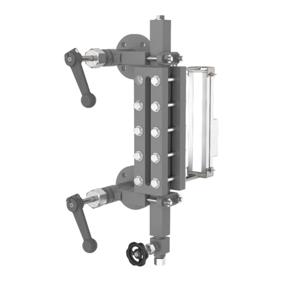
YSTEM ESCRIPTION 4 System Description 4.1 Function The transparent indicator is a direct water level gauge with an illumination device that is primarily used on pressurised tanks. Thanks to the brilliant LED backlighting, the fill level is clearly visible at all times. 4.2 Different variants Single sight length Staggered multiple sight lengths... -
Page 15: Construction
15.1 Holder for water level mark with screws (only for TG120) Threaded bolt 15.2 Water level mark with screws Washer Lighting equipment *for TG40 - 1 piece per side, for TG120 - 2 pieces per side, a TG120 is shown as an example D-03-B-50371-EN-02 Page 11... -
Page 16: Technical Data
ECHNICAL DATA 6 Technical data 6.1 Limitations of use Limitations of use TG40 all. Pressure [PS] all. Temperature [TS] Media with glass attack 32 bar 239 °C (e.g. water vapour) 464 psig 458 °F 40 bar 50 °C psig 122°F Media without glass attack (e.g. -
Page 17: Dimensions
One display opening Offset display openings The gauges shown are shown as a left-hand model of type TG40. The dimensions H and J are to be specified individually. The A-measurement is calculated using the sight length-E and the H and J dimensions. -
Page 18: Optional Versions
ECHNICAL DATA 6.4 Optional versions In addition to customer-specific drain and shutoff valves, the Transparent level gauge can also be customized with other features. These Installation and operating instructions also apply to these versions. For versions with other shut-off and drain valves and lighting devices, the documents for the installed valves must also be observed. -
Page 19: Assembly
SSEMBLY 7 Assembly 7.1 Version with flange • Observe the orientation of the gauge. • Check sealing surfaces for cleanliness • Install the flange connection between the gauge and the boiler/pressure vessel according to the applicable standard 7.2 Version with welding end ARNING Eye damage due to lack of personal protective equipment Lack of eye protection during welding leads to eye damage in working and bystanders. -
Page 20: Bending And Mounting The Water Level Mark
SSEMBLY 7.3 Bending and mounting the water level mark If the water level mark is not already mounted but is included with the gauge including screws, it must be bent as described below and mounted on the clamping tabs at the specified height. Bending the water level mark Fig.1 Fig.2... - Page 21 SSEMBLY Work steps Fig.1 Fig.2 Fig.3 Fig.4 Figure 1 • Stop the water level mark at the desired position and trace the oblong hole with a marker. Figure 2 • Punch holes to be drilled at a suitable distance from each other with a light hammer blow. Figure 3 •...
-
Page 22: Commissioning
When tightening the screws, ensure the following tightening sequence on the cover rails. Tighten the screw connection to the tightening torque in the prescribed sequence and in the prescribed steps. Screw rows Uneven number Even number Tightening torque Md → Md [Nm] in increments TG40 TG120 Page 18 D-03-B-50371-EN-02... -
Page 23: Commissioning At The Same Time As The Boiler
The pH value of the medium has a strong effect on the removal of the reflective glass. 8.2 Commissioning at the same time as the boiler This type of commissioning is recommended by Igema GmbH due to the lower stress on the components. -
Page 24: Commissioning Under Pressure And Temperature Loads
OMMISSIONING 8.3 Commissioning under pressure and temperature loads Fig.1 Fig.2 Fig.3 Fig.4 Fig.5 Figure 1: ▪ The gauge must be depressurised (chap.9.2) • Open the upper shutoff valve slowly. The gauge is heated to operating temperature by the steam flowing through it within 5-10min. -
Page 25: Servicing
It is necessary to make sure that the visible fill level coincides with the actual one. • Keeping glasses clean In order to ensure a trouble-free process, Igema GmbH recommends an annual replacement of the glass and the seals. Shorter maintenance intervals are recommended in extreme operating conditions. -
Page 26: Cleaning The Gauge / Depressurising
ERVICING Creation of a maintenance plan The operator must determine a maintenance plan suitable for the specific application after evaluating his own operating experience. It should be noted that shorter maintenance intervals extend the service life of the level gauge. 9.2 Cleaning the gauge / depressurising Fig.1 Fig.2... -
Page 27: Cleaning The Mica Shields
ERVICING ▪ The gauge must be depressurised Figure 1: • Open the upper shutoff valve slowly. • The steam flowing through cleans the mica. Figure 2: • Close the upper shutoff valve. • Close the drain valve. The gauge can be put back into operation. (chap.8) 9.4 Cleaning the mica shields Fig.1 Fig.2... -
Page 28: Glass/Mica Replacement
ERVICING 9.5 Glass/mica replacement Property damage caused by damaged components Components that appear to be intact can be damaged and lead to damage to the gauge when reinstalled or reused. • Replace glasses, mica and seals annually. • After loosening the cover rails, install completely new seals. •... - Page 29 ERVICING The cover rail can be loosened by engaging it at the side with a slotted screwdriver using lever movements. Figure 3: • Remove the seals, glasses and mica shields on both sides of the gauge. • Remove any sealing residue from the sealing surface of the display body and the contact surface of the cover rail, clean and check for damage.
-
Page 30: Case Of Damage
ASE OF DAMAGE 10 Case of damage Fault Possible cause Remediation Leakage on the glass holder Tighten the screws on the between the body and the Wear and tear cover rail graphite gasket (chap.10.1) Tighten hexagon nuts / Leakage between sealing ring Wear and tear replace sealing ring and shutoff valve... -
Page 31: Leakage Between Sealing Ring And Shutoff Valve
ASE OF DAMAGE 10.2 Leakage between sealing ring and shutoff valve Fig.1 Fig.2 Fig.3 Fig.4 Figure 1: • Retighten hexagon nuts with Md =65Nm. Figure 2: ▪ If there is no improvement, take the following steps after relieving pressure: • Loosen the hexagon nuts of the valves. •... -
Page 32: Leakage Between The Screw Plug And The Display Body
ASE OF DAMAGE 10.3 Leakage between the screw plug and the display body Fig.1 Fig.2 Fig.3 Figure 1: • Tighten the torque of the screw plug Figure 2: ▪ If there is no improvement: • Unscrew the screw plug • Replace the gasket. •... -
Page 33: Spare Parts And Technical Accessories
= number of sight openings. For offset banner displays, pos. no.: 1&2 must be ordered 5 times in total. Spare parts package 3,4,5 consisting of: for TG40 4x seal, 2x transparent glass and 2x mica shields for TG120 4x seal, 2x transparent glass and 4x mica shields... -
Page 34: Accessories
Property damage caused by incorrect spare parts Replaced spare parts that do not correspond to the characteristics of the original spare parts may cause damage to the gauge. • Only use original parts from Igema GmbH for replacement. Page 30 D-03-B-50371-EN-02... -
Page 35: Decommissioning And Disposal
ECOMMISSIONING AND DISPOSAL 12 Decommissioning and disposal 12.1 Dismantling the display body Fig.1 Fig.2 Figure 1: ▪ The gauge must be depressurised • Loosen the hexagon nuts of the valves, unscrew and remove together with the clamping brackets. • The display hangs freely after this step and must be secured against falling. Property damage due to impacts When handling the gauge, it may be damaged by impacts. -
Page 36: Disposal
Residues of hazardous substances pose a health hazard. • Indicate possible dangers and take precautionary measures. This high-quality IGEMA product was designed, manufactured and tested with the application of the QM System guidelines in accordance with DIN EN ISO 9001:2015. - Page 40 Direct Download Product page on the Internet Igema GmbH Antwerpener Str. 1 Phone: +49 2501 924 24 0 48163 Muenster Fax: +49 2501 924 24 99 Germany info@igema.com www.igema.com...
Need help?
Do you have a question about the TG40 and is the answer not in the manual?
Questions and answers