
Related Manuals for Igema RBA 26/36


Summary of Contents for Igema RBA 26/36
- Page 1 Fill level controller and limiter RBA 26/36 Version 05/2024 D-07-B-50223-EN-02 Installation and operating instructions (English translation)
-
Page 2: Table Of Contents
Table of Contents About this document Introduction __________________________________________________ 1 Product identification and rating plate ______________________________ 2 Related documents ____________________________________________ 3 Marking of safety precautions ____________________________________ 4 Copyright ____________________________________________________ 4 Safety Instructions Requirements for personnel ______________________________________ 5 Safety at work ________________________________________________ 5 Intended use _________________________________________________ 7 Damage to the product _________________________________________ 8 Contents of the packaging... - Page 3 Blowing through the connecting lines ______________________________ 26 Condition check during boiler overhaul ____________________________ 28 Case of damage 10.1 Replace magnetic lock switch ___________________________________ 31 Spare parts 11.1 RBA 26/36 __________________________________________________ 33 Decommissioning and disposal 12.1 Dismantling the float switch _____________________________________ 34 12.2 Disposal ____________________________________________________ 35...
-
Page 5: About This Document
Installation and operating instructions must also be included in the national language of the third party. OTICE Safe and trouble-free operation of the Igema GmbH Fill level controller and limiter is not possible without precise knowledge of the individual components. •... -
Page 6: Product Identification And Rating Plate
BOUT THIS DOCUMENT 1.2 Product identification and name plate On the basis of the name plate, the Installation and operating instructions can be assigned to the corresponding Fill level controller and limiter. The Installation and operating instructions belongs to the Fill level controller and limiter of the type RBA 26/36. -
Page 7: Related Documents
In addition to this Installation and operating instructions, the operating instructions for the blow- through and drain valves and the data sheet for the globe valves must be observed. Document number/ Product QR-Code Link Blow-through valves 63373 WA4, WA5 & WA6 www.igema.com/document/63373 Globe valves 50546 WA3, WA10 www.igema.com/document/50546 62825 Drain valves www.igema.com/document/62825 D-07-B-50223-EN-02... -
Page 8: Marking Of Safety Precautions
This Installation and operating instructions contains texts and drawings that may not be reproduced, distributed or otherwise communicated in whole or in part without the express permission of the manufacturer. The copyright of the operating instructions remains with: Igema GmbH Antwerpener Str. 1 48163 Muenster Germany Violations oblige you to pay compensation. -
Page 9: Safety Instructions
Only qualified persons who are familiar with the measurement and control systems are allowed to carry out work. Only trained electricians may install and connect electrical equipment. Igema GmbH can be commissioned for the installation and maintenance. AUTION Risk of injury due to external influences External influences can lead to injuries in the absence of protective equipment •... - Page 10 AFETY NSTRUCTIONS ARNING Risk of injury due to leaking medium Inflammatory, irritating and harmful substances can escape from the gauge and lead to skin injuries and burns. This danger is also to be expected in the case of an unpressurised cooled system.
-
Page 11: Intended Use
AFETY NSTRUCTIONS AUTION Risk of injury due to unsecured working area An unsecured working area can endanger working and bystanders. • Ensure safe access. • Delimit and mark the secured working area. • Sufficiently illuminate the working area. Risk of injury due to heavy loads There is a risk of injury when handling large and/or heavy gauges. -
Page 12: Damage To The Product
AFETY NSTRUCTIONS 2.4 Damage to the product OTICE Property damage caused by incorrect storage and transport Incorrect transport and storage can cause damage to the float switch. • Avoid bumps and hard setdown. • Store the float switch protected from environmental influences and in a dry place. •... -
Page 13: Contents Of The Packaging
ONTENTS OF THE PACKAGING Contents of the packaging 3.1 Included 1. RBA 26/36 The Fill level controller and limiter will be delivered as a pre-assembled unit, unless otherwise contractually agreed: • Gauge • Drain valve / screw plug 2. Installation and operating instructions... -
Page 14: System Description
YSTEM ESCRIPTION System Description 4.1 Function The RBA26/36 float switch can be used as a two-point water level controller or water level limiter without a special design for steam generators. The float switches, in different versions, are used to control or limit the water level in tanks and steam generators. -
Page 15: Construction
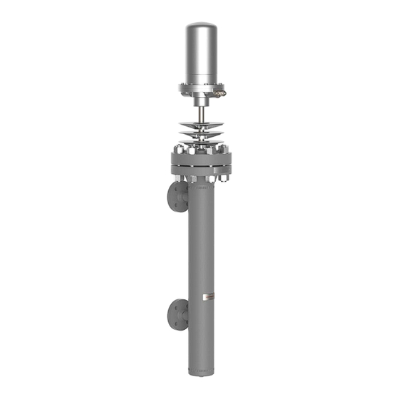
ONSTRUCTION Construction 5.1 Construction 1.1 Magnetic locking switch M130-KG Transducer tube 1.2 Lower part of switch housing Mounting housing 1.3 Switch housing cover Drain valve / drain plug 1.4 Sealing ring Upper blow-through valve Float Lower blow-through valve Float device Upper flow valve 4.1 Threaded bolt Bottom flow valve... -
Page 16: Basic Equipment
ONSTRUCTION 5.2 Basic equipment The float switch is supplied with a G " drain plug and a switch housing in accordance with protection class DIN VDE 0470: IP54 with built-in magnetic lock switch M130-KG. Customer specific equipment is possible. Screw plug G "... -
Page 17: Technical Data
ECHNICAL DATA Technical data 6.1 Operating limit Operating limit RBA 26/36 perm. Pressure [PS] perm. Temperature [TS] 100 bar 311 °C PN160 1450 psig 591 °F 120 bar 325 °C PN250 1740 psig 617 °F The maximum permissible operating pressure of the Fill level controller and limiter is determined by the lowest permissible pressure of the attached component. -
Page 18: Dimensions
ECHNICAL DATA 6.3 Dimensions Gauge Pressure stage [PS] [mm] [inch] [mm] [inch] Connection dimension [A1] Connection depth Connection distance A+D+800 A+D+31 A+D+800 A+D+31 The component label is only valid if shut-off valves are fitted between the process connection and the boiler connection and a drain valve is fitted to the drain connection. - Page 19 ECHNICAL DATA Magnetic locking switch [mm] [inch] Installation depth Total depth Width Height D-07-B-50223-EN-02 Page 15...
-
Page 20: Assembly
SSEMBLY Assembly 7.1 Version with flange • Observe the orientation of the gauge. • Check sealing surfaces for cleanliness • Install the flange connection between the gauge and the boiler/pressure vessel according to the applicable standard 7.2 Version with welding end ARNING Eye damage due to lack of personal protective equipment Lack of eye protection during welding leads to eye damage in working and bystanders. -
Page 21: Power Connection
The VDE regulations and the specifications of the local grid operator corresponding to these regulations must be observed when installing the magnetic circuit breaker. Igema GmbH recommends using acetic acid-free silicone cable for the connecting cable inside the connection housing. -
Page 22: Connecting The Magnetic Lock Switch Electrically
Only trained electricians may commission electrical components and carry out maintenance work on them. Igema GmbH can be commissioned for work on electronic components. Connection as SPDT circuit (standard) Magnet above the switch Magnet below the switch... - Page 23 SSEMBLY OTICE Installation of the switch in circuits after risk assessment Safety principles in accordance with DIN EN ISO 13849 with regard to safety-relevant circuits (e.g. PLC) in which the switch is installed must be observed. Delayed switching due to switching time •...
-
Page 24: Commissioning
OMMISSIONING Commissioning 8.1 Before commissioning Torque Tightening torque perm. Md → Md [Nm] pressure in steps [bar] Magnetic locking switch • Ensure that the magnetic lock switch is firmly attached to the transducer tube. 8.2 Commissioning the device simultaneously with the boiler Fig.1 Figure 1: •... -
Page 25: Commissioning The Device When The Boiler Is Under Pressure
OMMISSIONING 8.3 Commissioning the device when the boiler is under pressure Fig.1 Fig.2 Figure 1: • Close the drain valve. • Open the lower shut-off valve slowly. Figure 2: • Open the upper shut-off valve slowly. D-07-B-50223-EN-02 Page 21... -
Page 26: After Commissioning
OMMISSIONING 8.4 After commissioning ARNING Risk of injury due to electrical voltage Electrical voltage can lead to injuries when touching conductive cables. • De-energise the system before maintenance work. During operation, check the setting of the magnetic locking switch and adjust the height if necessary. - Page 27 OMMISSIONING Figure 1: • Loosen the screws on the housing cover and remove the housing cover. Figure 2: • Slightly loosen the screw on the switch base. The magnetic lock switch can be moved on the switch rod. • Move the magnetic lock switch to the appropriate height and hold it in place. Figure 3: •...
-
Page 28: Maintenance And Operational Monitoring
AINTENANCE AND OPERATIONAL MONITORING Maintenance and operational monitoring 9.1 Functional test OTICE Mandatory functional check A functional test is mandatory for water level limiters before commissioning. • Specify the scope of testing and testing deadlines between the operator, boiler supplier and local expert. Fig.1 Fig.2 Fig.3... -
Page 29: Release Pressure
AINTENANCE AND OPERATIONAL MONITORING 9.2 Release pressure Fig.1 Figure 1: • Close shut-off valves • Open the drain valve The gauge is emptying. The gauge can be put back into operation. (Chap.8) D-07-B-50223-EN-02 Page 25... -
Page 30: Blowing Through The Connecting Lines
AINTENANCE AND OPERATIONAL MONITORING 9.3 Blowing through the connecting lines OTICE For water level controllers and limiters, separate blowing through of the connecting lines including the attachment housing is required. Fig.1 Fig.2 Fig.3 Fig.4 Page 26 D-07-B-50223-EN-02... - Page 31 AINTENANCE AND OPERATIONAL MONITORING ▪ The gauge must be depressurised. Figure 1: • Open upper shut-off valve slightly, close after approx. 2 seconds. Figure 2: • Open lower shut-off valve slightly, close after approx. 2 seconds. Figure 3: • Close the drain valve. •...
-
Page 32: Condition Check During Boiler Overhaul
AINTENANCE AND OPERATIONAL MONITORING 9.4 Condition check during boiler overhaul During the boiler inspection, check that the float switch, in particular the float device, magnetic locking switch and the associated shut-off valves are in perfect condition. OTICE Malfunction due to bent float rod A bent float rod can cause the float to tilt in the mounting housing. - Page 33 AINTENANCE AND OPERATIONAL MONITORING Checking or replacing float device Fig.1 Fig.2 Fig.3 Fig.4 Opening the mounting housing Figure 1: • Bend out the retaining spring and loosen the encoder tube cap. Figure 2: • Pull the float rod with float out of the transducer tube •...
- Page 34 AINTENANCE AND OPERATIONAL MONITORING Closing the mounting housing Fig.1 Fig.2 Fig.3 Figure 1: • Check that the sealing surfaces of the device flanges are in perfect condition. • Place a new gasket between the flanges on the mounting housing. Figure 2: •...
-
Page 35: Case Of Damage
ASE OF DAMAGE 10 Case of damage Fault Possible cause Remediation Bent float rod, defective Check float device, replace float if necessary (chap. 9.4) Float does not float Depressurise (chap. 9.2) Contamination in mounting Blow through connection housing lines (chap. 9.3) Magnetic lock switch does not Replacing the magnetic Defective switch... - Page 36 ASE OF DAMAGE Figure 1: • Loosen the screws on the switch housing cover. • Remove the switch housing cover. Figure 2: • Loosen the cable gland of the cables of the switch to be removed. • Pull out the cable. Figure 3: •...
-
Page 37: Spare Parts
PARE PARTS 11 Spare parts 11.1 RBA 26/36 Quantit Pos. Description Size Article-No. Magnetic locking switch M130- 15-01122 3 balls 15-14511 100 bar 4 balls 15-14514 5 balls 15-14515 6 balls 15-14516 Float 7 balls 15-14517 120 bar 8 balls... -
Page 38: Decommissioning And Disposal
ECOMMISSIONING AND DISPOSAL 12 Decommissioning and disposal 12.1 Dismantling the float switch During the following work, the individual components hang freely and must be secured against falling. • Loosen nuts on flange connections. • Removing bolts from flanges • Secure loose components against falling Fig.1 Valves and gauges that are firmly connected to each other (e.g. -
Page 39: Disposal
Residues of hazardous substances pose a health hazard. • Indicate possible dangers and take precautionary measures. This high-quality IGEMA product was designed, manufactured and tested with the application of the QM System guidelines in accordance with DIN EN ISO 9001:2015. - Page 44 Direct Download Product page on the Internet Igema GmbH Antwerpener Str. 1 Phone: +49 2501 924 24 0 48163 Muenster Fax: +49 2501 924 24 99 Germany info@igema.com www.igema.com...
Need help?
Do you have a question about the RBA 26/36 and is the answer not in the manual?
Questions and answers