
Related Manuals for Igema TG200


Summary of Contents for Igema TG200
- Page 1 Transparent gauge TG200 - lateral Version 03/2024 D-03-B-51284-EN-03 Installation and operating instructions (English translation)
-
Page 2: Table Of Contents
Table of Contents About this document Introduction __________________________________________________ 1 Product identification and rating plate ______________________________ 2 Related documents ____________________________________________ 3 Marking of safety precautions ____________________________________ 4 Copyright ____________________________________________________ 4 Safety Instructions Requirements for personnel ______________________________________ 5 Safety at work ________________________________________________ 5 Intended use of the gauge _______________________________________ 7 Damage to the product _________________________________________ 7 Contents of the packaging... - Page 3 Commissioning Before commissioning _________________________________________ 18 Commissioning at the same time as the boiler_______________________ 19 Commissioning under pressure and temperature loads ________________ 20 Servicing Preventive maintenance _______________________________________ 21 Cleaning the gauge / depressurising ______________________________ 22 Blowing through the gauge for further cleaning ______________________ 23 Cleaning the mica ____________________________________________ 23 Changing the mica ____________________________________________ 24 Case of damage...
-
Page 5: About This Document
1 About this document 1.1 Introduction The Installation and operating instructions are part of the Transparent gauge TG200 - lateral. It must be made available to the responsible departments "Incoming goods, transport, assembly, commissioning and maintenance". The Installation and operating instructions must be stored in such a way that the specialist personnel has access to them at all times. -
Page 6: Product Identification And Rating Plate
Transparent gauge. The Installation and operating instructions belongs to the Transparent gauge of the type TG200 - lateral. Additions that are entered after the designation and describe the design of the Transparent gauge (e.g. 5/3ü) do not release these Installation and operating instructions from belonging to the Transparent gauge. -
Page 7: Related Documents
In addition to these Installation and operating instructions, the operating instructions of the shut-off and drain valves as well as the lighting system must be observed. Operating instruction number/ Product QR-Code Link 61253 Shutoff valve www.igema.com/document/61253 61254 Drain valves www.igema.com/document/61254 52057 LED Secure Slim www.igema.com/document/52057 51197 LED Secure Ex SOL W www.igema.com/document/51197... -
Page 8: Marking Of Safety Precautions
This Installation and operating instructions contains texts and drawings that may not be reproduced, distributed or otherwise communicated in whole or in part without the express permission of the manufacturer. The copyright of the operating instructions remains with: Igema GmbH Antwerpener Str. 1 48163 Münster Germany... -
Page 9: Safety Instructions
Only qualified persons who are familiar with the measurement and control systems are allowed to carry out work Igema GmbH can be commissioned for the installation and maintenance. AUTION Risk of injury due to external influences External influences can lead to injuries in the absence of protective equipment •... - Page 10 AFETY NSTRUCTIONS Risk of injury due to leaking medium Inflammatory, irritating and harmful substances can escape from the gauge and lead to skin injuries and burns. This danger is also to be expected in the case of an unpressurised cooled system. •...
-
Page 11: Intended Use Of The Gauge
AFETY NSTRUCTIONS Risk of injury due to heavy loads There is a risk of injury when handling large and/or heavy gauges. • Observe the load handling regulation. • Use lifting equipment to move heavy and bulky appliances. Risk of health damage due to noise Noise leads to damage to the health of the hearing. -
Page 12: Contents Of The Packaging
ONTENTS OF THE PACKAGING 3 Contents of the packaging 3.1 Included 1 TG200 - lateralThe Transparent gauge will be delivered as two pre-assembled units, unless otherwise contractually agreed: Unit A • Gauge • Upper shutoff valve • Lower shutoff valve •... -
Page 13: System Description Function
YSTEM ESCRIPTION 4 System Description 4.1 Function The transparent indicator is a direct water level gauge with an illumination device that is primarily used on pressurised tanks. The gauge works on the physics law of communicating tubes. The level can be clearly read on the sight glass of the gauge thanks to the backlighting. -
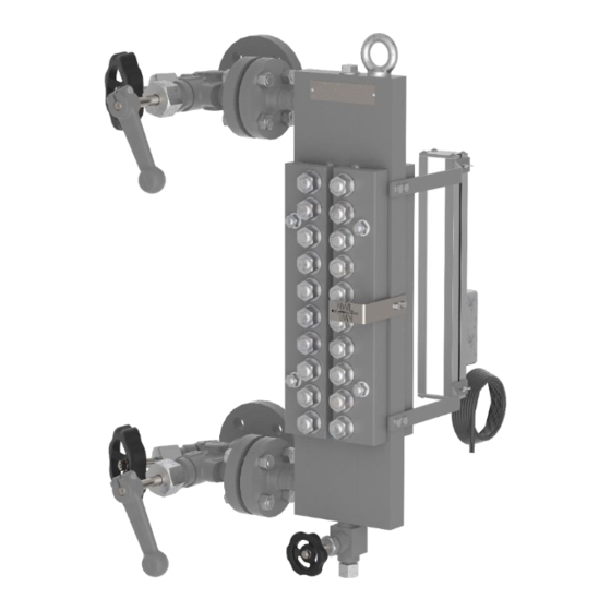
Page 14: Construction
ONSTRUCTION 5 Construction Screw plug Hexagon nut M16 Sealing ring Hexagon nut M10 Copper gasket Display body Mica packet Drain valve Pressure plate Upper shutoff valve Cover rail Lower shutoff valve Threaded bolt M16 Rating plate Threaded bolt M10 Water level mark Washer M16 Lighting equipment SMD package for flange... -
Page 15: Technical Data
ECHNICAL DATA 6 Technical data 6.1 Limitations of use Limitations of use TG200 - lateral all. Pressure [PS] all. Temperature [TS] 200 bar 367°C 2900 psig 692°F The maximum permissible operating pressure of the Transparent gauge is determined by the lowest permissible pressure of the attached component. -
Page 16: Dimensions
ECHNICAL DATA 6.3 Dimensions One display opening Display openings offset next to each other Both models are shown as left-hand models minimum [mm] [inch] Upper blind space Lower blind space Protrusion [Ü] Property damage due to weight loading If the total weight of the gauge 30kg the connecting elements are subjected to excessive >... -
Page 17: Optional Versions
ECHNICAL DATA 6.4 Optional versions In addition to customer-specific drain and shutoff valves, the Transparent gauge can also be customized with other features. These Installation and operating instructions also apply to these versions. For versions with other shut-off and drain valves, the documents for the installed valves must also be observed. -
Page 18: Assembly
SSEMBLY 7 Assembly 7.1 Version with flange • Observe the orientation of the gauge. • Check sealing surfaces for cleanliness • Install the flange connection between the gauge and the boiler/pressure vessel according to the applicable standard 7.2 Version with welding end ARNING Eye damage due to lack of personal protective equipment Lack of eye protection during welding leads to eye damage in working and bystanders. -
Page 19: Installing The Lighting System
Property damage caused by incorrect installation, commissioning, maintenance and operation Only trained electricians may install and connect lighting equipment. Igema GmbH can be commissioned for the installation and maintenance. Property damage caused by irregular use • Use the applicable documents to check whether the lighting device is intended for the planned use. -
Page 20: Fitting The Water Level Mark
SSEMBLY 7.4 Fitting the water level mark Components Designation Figure Quantity Water level mark M5 x 10 self-tapping screw, case-hardened steel Tools Designation Figure Recommended size Marker 0.6 mm linewidth Grain 4mm lace width Fitter's hammer 500g HSS Twist Drills Ø... - Page 21 SSEMBLY Work steps Fig.1 Fig.2 Fig.3 Fig.4 Figure 1 • Stop the water level mark at the desired position and trace the holes with a marker. Mark the drill holes as centrally as possible on the display body. Figure 2 •...
-
Page 22: Commissioning
OMMISSIONING 8 Commissioning 8.1 Before commissioning Torque All liquid level gauges are subjected to a pressure test before delivery. In individual cases, material placement may occur due to transport, storage or during assembly. Leaks due to insufficient torques • Check screw connections for appropriate torque and a tight fit. •... -
Page 23: Commissioning At The Same Time As The Boiler
The pH value of the medium has a strong effect on the removal of the reflective glass. 8.2 Commissioning at the same time as the boiler This type of commissioning is recommended by Igema GmbH due to the lower stress on the components. -
Page 24: Commissioning Under Pressure And Temperature Loads
OMMISSIONING 8.3 Commissioning under pressure and temperature loads Fig.1 Fig.2 Fig.3 ▪ The gauge must be depressurised (chap.9.2) Figure 1: • Slowly open the upper shut-off valve ( pos. 12) (hand lever in approx. 5 min. position) • The gauge is heated to operating temperature by the steam flowing through it within 5-10min. -
Page 25: Servicing
Replaced spare parts that do not correspond to the characteristics of the original spare parts may cause damage to the gauge. • Only use original parts from Igema GmbH for replacement. AUTION Cuts caused by sharp objects During the maintenance of the device, sharp-edged parts may cause injuries. -
Page 26: Cleaning The Gauge / Depressurising
ERVICING In order to ensure a trouble-free process, Igema GmbH recommends an annual replacement of the glass and the seals. Shorter maintenance intervals are recommended in extreme operating conditions. Creation of a maintenance plan The operator must determine a maintenance plan suitable for the specific application after evaluating his own operating experience. -
Page 27: Blowing Through The Gauge For Further Cleaning
ERVICING 9.3 Blowing through the gauge for further cleaning Fig.1 Fig.2 ▪ The gauge must be depressurised (chap.9.2) Figure 1 • Open the upper shutoff valve slowly (pos. 12) The steam flowing through cleans the glasses. Figure 2 • Close the upper shutoff valve (pos. -
Page 28: Changing The Mica
ERVICING 9.5 Changing the mica Dismantling the water level marker and lighting device beforehand provides more space and therefore makes the subsequent work easier. Property damage caused by damaged components Apparently intact components can be damaged and lead to damage to the device when reinstalled or reused. - Page 29 ERVICING Figure 1: ▪ The gauge must be depressurised. • Loosen the nuts on the cover and retaining screws and remove them together with the washer. • Remove the cover rails. Figure 2: • Loosen the retaining screws on the back and remove together with the washer. •...
-
Page 30: Case Of Damage
ASE OF DAMAGE 10 Case of damage Fault Possible cause Remediation Leakage on the glass holder Tighten the screws to the between the body and the Material settlements, wear specified torque (chap. graphite gasket 10.1) Carry out work on flange Leakage at flange connection Wear, stresses connections... -
Page 31: Leakage At Flange Connection
ASE OF DAMAGE 10.2 Leakage at flange connection Fig.1 Fig.2 Fig.3 Figure 1 • Tighten hexagon nuts to maximum torque in accordance with the prescribed standard. Figure 2: If there is no improvement: Property damage due to impacts The gauge hangs freely after the work in the following step. •... -
Page 32: Leakage Between The Screw Plug And The Display Body
ASE OF DAMAGE 10.3 Leakage between the screw plug and the display body Fig.1 Fig.2 Fig.3 Figure 1: • Tighten the torque of the screw plug Figure 2: If there is no improvement: • Unscrew the locking screw. • Replace the gasket. •... -
Page 33: Spare Parts And Technical Accessories
PARE PARTS AND TECHNICAL ACCESSORIES 11 Spare parts and technical accessories 11.1 Spare parts Designation Size Item no. Quantity pos. Screw plug " 40-10481 Sealing ring 21x26x1.5mm 40-00099 15-13096 15-13097 15-13098 Spare parts package 15-13099 15-13100 15-13101 15-13102 25-00077 n x 2 25-00078 n x 2 25-00079... -
Page 34: Accessories
(article no. 40-11364) Property damage caused by incorrect spare parts Replaced spare parts that do not correspond to the characteristics of the original spare parts may cause damage to the gauge. • Only use original parts from Igema GmbH for replacement. -
Page 35: Decommissioning And Disposal
ECOMMISSIONING AND DISPOSAL 12 Decommissioning and disposal 12.1 Dismantling the display unit Before dismantling the display body, disconnect the display unit from the power supply and remove it from the display body. To do this, loosen the fastening screws of the holding bracket and remove the lighting device. -
Page 36: Disposal
Residues of hazardous substances pose a health hazard. • Indicate possible dangers and take precautionary measures. This high-quality IGEMA product was designed, manufactured and tested with the application of the QM System guidelines in accordance with DIN EN ISO 9001:2015. - Page 40 Direct Download Product page on the Internet Igema GmbH Antwerpener Str. 1 Phone: +49 2501 924 24 0 Fax: +49 2501 924 24 99 48163 Muenster Germany info@igema.com www.igema.com...
Need help?
Do you have a question about the TG200 and is the answer not in the manual?
Questions and answers