
Related Manuals for Igema NA7-45


Summary of Contents for Igema NA7-45
- Page 1 Magnetic level indicator NA7-45 / NA7-130 Edition 07/2021 D-06-B-51014-EN-00 INSTALLATION AND OPERATING INSTRUCTION...
- Page 2 Product philosophy Thank you for placing your trust in IGEMA and deciding in favour of one of our high-quality products. For more than 100 years, measuring and control systems have been developed, produced and sold worldwide under the IGEMA brand name.
-
Page 3: Table Of Contents
Table of contents 1. Important safety instructions ................6 Symbols used in these instructions ..............6 Intended use of the device ................7 Safety at work ....................8 Safety instructions for this device..............9 Exclusion of liability ..................9 2. Contents of packing ..................10 3. - Page 4 Table of contents 7. Assembly ......................13 Version with flange ..................13 Version with welding end ................14 Heat treatment of weld seams ..............14 Flap indicator ....................14 Float installation .................... 14 Drain piping ....................14 Assembly of additional equipment (for retrofitting, otherwise already pre-installed) ....................
- Page 5 Table of contents 11. Drain valve ......................19 11.1 Construction ....................19 11.2 Assembly ...................... 20 11.3 Commissioning ..................... 21 11.4 Maintenance ....................21 12. Spare parts ......................22 12.1 Magnetic level gauge ..................22 12.3 Drain valve ....................22 13.
-
Page 6: Important Safety Instructions
Unqualified persons must not be assigned the above tasks! IGEMA GmbH accepts no liability for damage to property or personal injury caused by unqualified persons or by failure to observe these installation and operating instructions. If no sufficiently qualified person can be found, IGEMA GmbH can be commissioned with the installation/maintenance. -
Page 7: Intended Use Of The Device
The correct installation position, alignment and flow direction of the device must be observed! Before installing the IGEMA product on boilers or containers, it is essential to remove all protective covers and, if necessary, the protective film from rating plates and sight glasses. -
Page 8: Safety At Work
1.3 Safety at work Before installation or carrying out maintenance work on the device, safe access must be ensured and a secure working area with sufficient lighting must be defined and marked out. Always use lifting equipment for heavy loads! Danger Before starting any work, carefully check which liquids or gases are or have been in the pipeline. -
Page 9: Safety Instructions For This Device
IGEMA GmbH Mess- und Regelsysteme will assume no liability if the above regulations, instructions and safety precautions are not observed and followed. If they are not expressly listed in the installation and operating instructions, changes to an IGEMA device are carried out at the risk of the user. -
Page 10: Contents Of Packing
2 Mounting and operating instructions 3. Important information 3.1 Intended use Magnetic level gauge NA7-45 / NA7-130: The magnetic level gauge is a liquid level gauge which can be used for steam boilers and containers. The indication is made via a float operated magnetic system. -
Page 11: Technical Data
5. Technical data 5.1 Versions NA7 (version flange/cap) > 2,6m > 6m Possible vent connections Vent cap Flange Flange with vent flange Possible drain connections Flange with drain flange Flange with drain valve... -
Page 12: Type Of Connection
• To indicate a range > 2,6 m it is necessary to use 2 or more superposed indicating ledges. • For level gauges longer than 6 m, the unit will be delivered in divided version with intermediate flanges. 5.2 Type of connection Standard : flanges according to DIN or ASME On request... -
Page 13: Construction
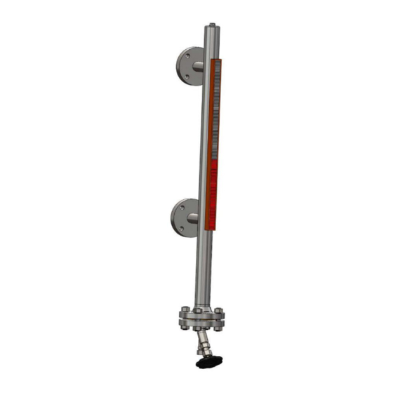
6. Construction Legend Connection studs Standpipe (2.1) Float (2.2) Sealing (2.3) Cover flange Flap indicator (3.1) Bolt spring (3.2) Stop clamp Magnetic switch (optional) Contact bar with reed contacts (optional) (Primary element MRK-…) Plug Drain valve (optional) Upper shutoff valve Lower shutoff valve 7. -
Page 14: Version With Welding End
7.2 Version with welding end • Observe installation position! • Remove protection caps from connection flanges. Caps only serve as transport protection. • Assembly only by using welding process 111 (manual arc welding) and 141 (tungsten inert gas welding). 7.3 Heat treatment of weld seams Supplementary temper tests of weld seams are not required. -
Page 15: Assembly Of Additional Equipment (For Retrofitting, Otherwise Already Pre-Installed)
7.7 Assembly of additional equipment (for retrofitting, otherwise already pre-installed) • Remove indicating ledge before assembly of additional equipment • Magnetic switches and/or primary element are fixed without obscuring the indication by means of integrated pipe saddle Assembly of magnetic switches or sensor may only be carried out in a maximum angle of 90°... -
Page 16: Magnetic Switch
8.1 Magnetic switch Contact position and wiring diagram: Float above the switch Float below the switch We recommend to use customary RC combinations or a suitable Varistor (e.g. 0,1 μF/100 Ω) as inductive consumer to extend the contact life of the magnetic switch. Resistance value (Ω) and power rating (W) depend on customer indications. -
Page 17: Commissioning Of Unit If Boiler Is Already In Operating Condition
9.3 Commissioning of unit if boiler is already in operating condition • Close drain valve (A) / plug (6) (see sketch chapter 6). • Open slowly shutoff valve W and then shutoff valve (D) • Check position of magnetic switch (2) in operating condition and adjust the height if necessary. -
Page 18: Tightening Torques
If this cleaning was not sufficient, dismount bottom/cover flange (2.3) and remove float (2.1). Plant must be pressureless for disassembly works! Wait until unit has cooled! Danger • Close shutoff valves (W+D). • Open drain valve (A) / plug (6); unit is drained. •... -
Page 19: Drain Valve
11. Drain valve 11.1 Construction AV500, AV520 • Male thread G½“ on input side • Output side with cutting ring connection ø 12 as per DIN 2353 – DS12 AV540, AV550 • Male thread G½” on input side • Output side with welding end •... -
Page 20: Assembly
AV56x, AV57x • Male thread G½” on input side • Output side with cutting ring connection ø12 as per DIN 2353 – DS12 • On request other connections possible Valve housing Screw cap Sealing ring Sealing ring Seat (10) Upper part of valve Valve spindle with cone (11) Handwheel... -
Page 21: Commissioning
11.3 Commissioning Rust, sand or similar impurities inside of the medium or during first flushing can cause leakage if they remain in the area of the seat. Purging of valve: • Fully open valve for purging. The pre-pressed gland packing can lose its denseness due to a longer storage (see chapter 11.4) •... -
Page 22: Spare Parts
Replacement of complete upper part: • For dismounting of component parts see “Replacement of packing” • Unscrew seat (3) with hexagon socket wrench AF11. • Grease seat thread, screw in and tighten with tightening torque M = 55 Nm. • Replace complete upper part. -
Page 23: Decommissioning
The magnetic switches are wear parts and are not included in the warranty. The sealings/gland packing installed in the valves are not included in the warranty. This high-quality IGEMA product was designed, manufactured and tested with the application of the QM System guidelines in accordance with DIN EN ISO 9001:2015. -
Page 24: Manufacturer´s Declaration
15. Manufacturer´s Declaration... - Page 28 IGEMA GmbH Antwerpener Str. 1 Fon.: +49 2501 92424-0 48163 Münster Fax.: +49 2501 92424-99 Deutschland info@igema.com www.igema.com...
Need help?
Do you have a question about the NA7-45 and is the answer not in the manual?
Questions and answers