
Related Manuals for Igema G


Summary of Contents for Igema G
- Page 1 Remote level gauge Type G Edition 03/2021 D-05-B-51518-EN-01 Installation and operating instructions...
- Page 2 Product philosophy Thank you for placing your trust in IGEMA and deciding in favour of one of our high-quality products. For more than 100 years, measuring and control systems have been developed, produced and sold worldwide under the IGEMA brand name.
-
Page 3: Table Of Contents
Table of contents 1. Important safety instructions ................6 1.1 Symbols used in these instructions ..............6 1.2 Intended use of the device ................7 1.3 Safety at work ....................8 1.4 Safety instructions for this device ..............9 1.5 Exclusion of liability ................... 9 2. - Page 4 Table of contents (cont.) 7. Assembly ......................15 7.1 Version with flange ..................15 7.2 Version with buttwelding end ................15 7.3 Remote level gauge (see sketch chapter 6) ............ 15 7.4 Illumination device ..................16 8. Commissioning ....................16 8.1 Before commissioning ..................
- Page 5 11.1 General information and operating instructions .......... 22 11.2 Construction of valves ................22 11.3 Indicator valve (h, j) ..................23 11.4 Main shutoff valve (c, g) ................24 12. Case of damage ....................25 13. Spare parts ......................25 13.1 Remote level gauge (see sketch chapter 6)..........
-
Page 6: Important Safety Instructions
Unqualified persons must not be assigned the above tasks! IGEMA GmbH accepts no liability for damage to property or personal injury caused by unqualified persons or by failure to observe these installation and operating instructions. If no sufficiently qualified person can be found, IGEMA GmbH can be commissioned with the installation/maintenance. -
Page 7: Intended Use Of The Device
The correct installation position, alignment and flow direction of the device must be observed! Before installing the IGEMA product on boilers or containers, it is essential to remove all protective covers and, if necessary, the protective film from rating plates and sight glasses. -
Page 8: Safety At Work
Avoid handling the device with your own physical force, e.g. by lifting, pulling, carrying, pushing or supporting it, especially to prevent back injuries. Use lifting equipment to move heavy and bulky equipment in accordance with Article 1, Section 2 of the German Load Handling Regulation (LasthandhabV). -
Page 9: Safety Instructions For This Device
For units with a dead weight of 30 kg or more, the customer must provide adequate support (e.g. via a spring suspension device, etc.). This can be attached to the holding strap/eyelet on the device. -
Page 10: Contents Of Packing
Caution Note! For displays weighing 30 kilograms or more, the customer must provide sufficient support (e.g. by spring hangers or similar). Caution 3.1 Intended use Remote level gauge: The remote level gauge type GS can be used for every steam generator according to TRD 401 except continuous steam generators. -
Page 11: Explanations
Explanations 4.1 Scope of supply The type FA GS is used to indicate the water level of steam generators. 4.2 Function The level gauge works according to the physical low of the communicating tubes. The geodetic pressure difference of two water columns is transferred to a transparent separating blue liquid in the remote level gauge. -
Page 12: Technical Data
Technical data 5.1 Version One sight opening... -
Page 13: Type Of Connection
IGEMA GmbH Mess- und Regelsysteme Antwerpener Straße 1 Germany – 48163 Münster * marking depending on the realization Date of manufacture Max. all. Temperature G TAG-Nr. (optional) Type of unit Nominal pressure (not listed) C Max. all. Pressure Nominal diameter... -
Page 14: Construction
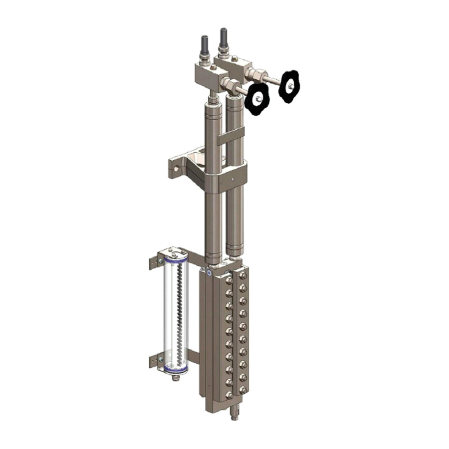
Construction Remote level gauge G Level gauge cross-section Steam Water Separating liquid Vent plug Level gauge Sealing Condenser Indicator fluid Glass Upper shut-off valve (m) Plug Sealing Bolting Plug (used as cushion) Balance pipe Supporting clamp Pressure plate Connection line... -
Page 15: Assembly
• Weld on connection bolting (d) on the ends of connection lines (f). Check sealing and sealing surface of the bolting (d). • Tighten firmly bolting (d) on condenser (b) and shutoff valve (g). • Mount illumination device (p) and carry out electrical connection observing the VDE 0100 and the current regulations. -
Page 16: Illumination Device
Commissioning Commissioning and maintenance must be carried out by qualified personnel! If no sufficiently qualified person can be employed, IGEMA GmbH can be commissioned to carry out the commissioning. In principle IGEMA GmbH recommends commissioning the indicator at the same time Danger as the boiler (item 8.2). -
Page 17: Cleaning Of Connection Lines (F) (See Sketch Chapter 5)
Info 8.2 Cleaning of connection lines (f) (see sketch chapter 5) • Close main shutoff valves (c) and (g). Detach connection lines (f) on indicator valves (h) and (j) and on bolting (d) and bend a little to the side. -
Page 18: Commissioning Of Remote Level Gauge
• Slowly fill in clean water up to overflowing at vent plug (a) of main shutoff valve (c). Both shutoff valves (c, g) must be closed. Tighten vent plug (a) with sealing • After having reached a minimum operating pressure of 2 bar, open valves in the following order: c, g, h and j. -
Page 19: Adjustment Of The Indicator Liquid Level
Open first indicator valve (h) and then valve (j). • Main shutoff valves (c, g) are not opened. Close opened indicator valves (h, j). Opening valves in the following order: c, g, h and j. • Condenser (b) is not hot enough; no condensation. -
Page 20: Decommissioning Of Boiler
It is assumed that the person charged with the maintenance tasks is fully conversant with measurement and control systems. Untrained persons must not carry out maintenance work! If there is no adequately qualified person available, IGEMA GmbH can be brought in to service your measurement and control system. -
Page 21: Cleaning Of Connection Lines (F) (See Sketch Chapter 6)
Commissioning of level gauge as described under point 8.2 / 8.3. 10.2 Cleaning of level gauge Close indicator valves (h, j). Carefully unfasten plug (n) on main shutoff valves (c, g) to relieve high pressure of level gauge (k). Remove plug (n). -
Page 22: Tightening Torques
>100 11. Shutoff valves 11.1 General information and operating instructions IGEMA valves are mostly maintenance-free and easy to handle. All IGEMA valves are equipped with metal gaskets and hand operation. Sealing of valve spindle is made with a gland packing. -
Page 23: Indicator Valve (H, J)
Cap nut 11.3 Indicator valve (h, j) Carry out maintenance works only if connection line (f) is empty and pressureless! Beware of escaping steam! Danger • Close valves (h, j, c and g) and carefully turn vent plug (a) once. -
Page 24: Main Shutoff Valve (C, G)
Insert upper part of valve (5) with valve spindle (10) and new sealing ring (4) in valve housing (1) and tighten. 11.4 Main shutoff valve (c, g) Carry out maintenance works only if boiler is pressureless and empty below valve stud. -
Page 25: Case Of Damage
Check if no further steam escapes at the damaged place. • Set boiler pressureless! Close valves as follows: • Close the upper and lower shut-off valves (c+g) on the steam- and water-carrying connections. • Close the indicator valve (h+j) on the steam- and water-carrying connection piece. •... -
Page 26: Spare Parts
13. Spare parts Always indicate article no. and serial no. (indicated on the identification plate) in case of spare parts order!! 13.1 Remote level gauge (see sketch chapter 6) for S=310 Article- No. Pos. Quantity Designation Material ≤100 >100 40-04443 Blue indicator fluid 1,68 40-00247... -
Page 27: Main Shutoff Valve
13.2 Main shutoff valve Pos. Article- No. Qty. Designation Material 15-00297 Cone set with seat 1.4034 / 1.4104 condenser 40-00099 Sealing ring 1.0338.03 40-00331 Screw plug 1.0711 40-00120 Sealing ring 1.0338.03 6,7,8 15-00112 Stuffing box packing Graphite 25-00662 Screw cap 1.0711 15-02690 Spindle... -
Page 28: Decommissioning
Dismount unit and separate waste products. When disposing the unit, observe legal regulations for waste disposal. This high-quality IGEMA product was designed, manufactured and tested with the application of the QM System guidelines in accordance with DIN EN ISO 9001:2000. -
Page 29: Manufacturer´s Declaration
Kommentiert [FN1]: Email an Claudius! 15. Manufacturer´s declaration ?????
Need help?
Do you have a question about the G and is the answer not in the manual?
Questions and answers