
Related Manuals for Igema TG32


Summary of Contents for Igema TG32
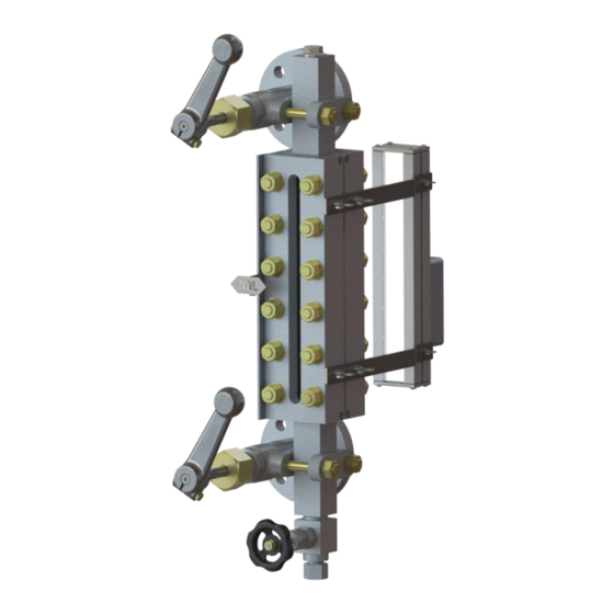
- Page 1 Transparent Level Gauge TG32 / TG120 Edition 11/2020 D-03-B-50371-EN-01 ASSEMBLY AND OPERATING MANUAL...
- Page 2 Product philosophy Thank you for placing your trust in IGEMA and deciding in favour of one of our high-quality products. For more than 100 years, measuring and control systems have been developed, produced and sold worldwide under the IGEMA brand name.
-
Page 3: Table Of Contents
Safety instructions for this device ..............8 Exclusion of liability ..................8 2. Contents of packing ................... 8 3. The Transparent Level Gauges TG32 and TG120 ........... 9 Device versions ..................... 9 Identification plate/ Marking ................. 10 Intended use ....................10 Function description .................. - Page 4 Table of contents (cont.) 7. Commissioning and maintenance phase ............15 7.1. Commissioning and maintenance requirements .......... 15 Commissioning the indicator at the same time as the boiler ......16 Starting up the indicator when the boiler is under pressure and Temperature stands ..................
-
Page 5: Important Safety Instructions
Unqualified persons must not be assigned the above tasks! IGEMA GmbH accepts no liability for damage to property or personal injury caused by unqualified persons or by failure to observe these installation and operating instructions. If no sufficiently qualified person can be found, IGEMA GmbH can be commissioned with the installation/maintenance. -
Page 6: Intended Use Of The Device
The correct installation position, alignment and flow direction of the device must be observed! Before installing the IGEMA product on boilers or containers, it is essential to remove all protective covers and, if necessary, the protective film from rating plates and sight glasses. -
Page 7: Safety At Work
1.3 Safety at work Before installation or carrying out maintenance work on the device, safe access must be ensured and a secure working area with sufficient lighting must be defined and marked out. Always use lifting equipment for heavy loads! Danger Before starting any work, carefully check which liquids or gases are or have been in the pipeline. -
Page 8: Safety Instructions For This Device
IGEMA GmbH Mess- und Regelsysteme will assume no liability if the above regulations, instructions and safety precautions are not observed and followed. If they are not expressly listed in the installation and operating instructions, changes to an IGEMA device are carried out at the risk of the user. -
Page 9: The Transparent Level Gauges Tg32 And Tg120
3. The Transparent Level Gauges TG32 and TG120 3.1 Device versions The transparent level gauges TG32 and TG120 are available as standard in two variants, one with a simple sight length and one with sight lengths offset to each other. In the offset variant there is always an overhang of 26mm to the opposite sight length. -
Page 10: Identification Plate/ Marking
3.2 Identification plate/ Marking The following data are indicated on the identification plate: IGEMA GmbH Mess- und Regelsysteme Antwerpener Straße 1 Germany – 48163 Münster * marking depending on the realization A - Date of manufacture + order number B - Type of unit C - Max. -
Page 11: Assembly
3.5 Assembly (1) Hexagonal nut Example staggered version (2) Washer (3) Threaded bolt (4) Cover rail (5) Mounting late of water level mark (6) Fastening screw (7) Set screw (mounting aid) (8) Graphite gasket (glass protection) (9) Borosilicate glass (10) Mica shield (TG120) (11) Graphite gasket (12) Base body... -
Page 12: Technical Data
4. Technical Data 4.1 Device dimensions One sight glass opening Sight glass openings offset to each other Ü=min. 26mm *L=Abhängig vom Prozessanschluss *L=Abhängig vom Prozessanschluss The dimensions H/J, E and A are stated in your order and can be viewed. All other dimensions can be found in the following tables. -
Page 13: Limitation Of Use
For steam applications, the following application limits apply to both the single inspection length and the offset version. The values given here must under no circumstances be exceeded!! Caution TG32 TG120 Max. Pressure 32bar / 464,1psi 120bar / 1740,5 psi Max. -
Page 14: Corrosion Resistance
5. General Information on the Shutoff Valve 5.1 Information IGEMA shutoff valves are mostly maintenance-free and easy to handle. All IGEMA valves are equipped with metal gaskets, the valve spindles are sealed with a gland packing. The shutoff valve versions go from simple shutoff (designation A1--) to double shutoff (designation A2--). -
Page 15: General Information On The Drain Valve
7.1. Commissioning and maintenance requirements Commissioning and maintenance must be carried out by qualified personnel! If no sufficiently qualified person can be employed, IGEMA GmbH can be commissioned to carry out the commissioning. In principle IGEMA GmbH recommends commissioning the indicator at the same time Danger as the boiler (point 7.2). -
Page 16: Commissioning The Indicator At The Same Time As The Boiler
Tightening sequence to be observed for the cover rails is presented below! Non-compliance may result in leakage, glass and mica break. Caution The following tightening sequence must be ensured at the cover rails (drawing below). Non- compliance can lead to leaks, which are not covered by the warranty. In the first step with 1. Md=20 Nm, in the second step with 2. -
Page 17: Starting Up The Indicator When The Boiler Is Under Pressure And Temperature Stands
Next, slowly and carefully open the upper stop valve (A1) a little so that the glass (TG32) or or mica (TG120) is carefully heated. Then the upper stop valve closes again. Now the upper stop valve (A1) can... -
Page 18: Cleaning The Glass Or Mica Shields
For safety reasons and to ensure full use of the indicator, glasses, mica and gaskets must always be replaced annually. Without the annual replacement IGEMA will not accept any warranty if this causes damage to the sealing surfaces of the indicator body. -
Page 19: Fitting
Caution, if defects or other damage arise during dismantling, it is essential that they are removed before the gauge is put back into operation, please contact the customer service of your contract partner or of IGEMA GmbH. Caution 7.7.2 Fitting Fit mica packets with the surface marked “Wasserseite (water side)”... -
Page 20: Maintenance Work On Shutoff Valve
7.8 Maintenance work on shutoff valve Do not carry out maintenance tasks and dismantling unless the boiler and level gauge are empty and depressurised. Gefahr Always keep shutoff valve spindle thread greased. Caution Replacing the packing set on the shutoff valve The following items must be renewed As an example: A120-CS when changing the packing set: item: 1... -
Page 21: Maintenance Work On Drain Valve
7.9 Maintenance work on drain valve Dismantle only when the level indicator is depressurised and empty. Gefahr In case of defects and leaks, the complete drain valve must be Drain valve AV250 replaced! The exchanging of the valve may only be carried out by specialists! Vorsicht Loosen the pipe screw connection from the drain valve and pull... -
Page 22: Faults, Troubleshooting And Customer Service
To put the level gauge back into operation, see section 8. 8.2 Technical customer service Our competent team at IGEMA GmbH will be happy to answer any questions you may have. In order to be able to ensure smooth service, please provide the following details: •... -
Page 23: Accessories
No.: offset to each length other Locking screws set G½" 40-00481 Sealing ring for G½" 40-00099 Spare Part Set TG32 Spare Part Set 15-13557 Spare Part Set 15-13558 Spare Part Set 15-13559 Spare Part Set 15-13560 Spare Part Set 15-13561... -
Page 24: Decommissioning
Dismount unit and separate waste products. When disposing the unit, observe legal regulations for waste disposal. Caution This high-quality IGEMA product was designed, manufactured and tested with the application of the QM System guidelines in accordance with DIN EN ISO 9001:2015. -
Page 25: Manufacturer's Declaration
12. Manufacturer’s Declaration... - Page 26 Link to TG32 Link to TG120...
- Page 28 IGEMA GmbH Antwerpener Str. 1 Fon.: +49 2501 92424-0 48163 Münster Fax.: +49 2501 92424-99 Deutschland info@igema.com www.igema.com...
Need help?
Do you have a question about the TG32 and is the answer not in the manual?
Questions and answers