HIKOKI C 12RSH3 Handling Instructions Manual
Hide thumbs
Also See for C 12RSH3:
- Handling instructions manual (328 pages) ,
- Handling instructions manual (92 pages)
Table of Contents
Advertisement
Quick Links
Advertisement
Table of Contents

Related Manuals for HIKOKI C 12RSH3


Summary of Contents for HIKOKI C 12RSH3
- Page 1 C 12RSH3 Handling instructions...
- Page 3 4 – ø9 mm 327 mm 282 mm...
- Page 6 ⓐ ⓑ ⓐ ⓑ ⓐ ⓑ...
- Page 7 2–3 mm...
- Page 8 14, 30 82, 83...
- Page 10 6 mm 17 mm 230V...
-
Page 12: General Power Tool Safety Warnings
c) Prevent unintentional starting. Ensure the GENERAL POWER TOOL SAFETY switch is in the off-position before connecting WARNINGS to power source and/or battery pack, picking up or carrying the tool. Carrying power tools with your finger on the switch WARNING or energising power tools that have the switch on Read all safety warnings, instructions, illustrations invites accidents. -
Page 13: Safety Instructions For Miter Saw
Slippery handles and grasping surfaces do not allow Small debris or loose pieces of wood or other objects for safe handling and control of the tool in that contact the revolving blade can be thrown with high unexpected situations. speed. 9. -
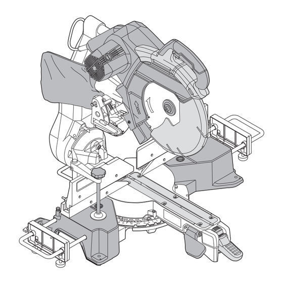
Page 14: Names Of Parts
21. Do not use saw blades manufactured from high speed steel. Switch lock 22. Use only saw blades recommended by HiKOKI. Motor head 23. The saw blades should be 305 mm external diameter. 24. Select the correct saw blade for the material to be cut. - Page 15 Holder (A) 8 mm set screw (For left 45° bevel angle) Hinge 8 mm set screw (For right angle) Indicator (For bevel scale) 8 mm set screw Set pin (A) (For right 45° bevel angle) Sub fence (B) 8 mm depth adjustment bolt Fence (B) 5 mm machine screw Base 6 mm wing bolt...
-
Page 16: Standard Accessories
Hose (id 38 mm) Always wear eye protection. Adapter (Dust extractor's standard accessory) Joint (C) (Optional accessory) Always wear hearing protection. Dust collection adapter (Optional accessory) Hose band (Optional accessory) Do not stare at operating lamp. Duct Washer (B) Warning 8 mm hex. bar wrench Washer (A) Class II tool Base grip... -
Page 17: Prior To Operation
Table 1: Max. sawing dimension 8. Installing the dust bag, sub table assembly, stopper and vises (The stopper is an optional Max. sawing dimension accessory.) Head Turntable (1) Installing the dust bag (Fig. 6) Max. height Max. width Install the dust bag onto the dust port on the miter saw. Fit the connecting tube of dust bag and the dust port 105 mm 312 mm... -
Page 18: Prior To Cutting
11. Checking the saw blade lower limit position 3. Confirmation for use of sub fence (B) (Fig. 12) Check that the saw blade can be lowered 9 mm to WARNING 11 mm below the table insert. When left bevel angle cutting, loosen the 6 mm wing When you replace a saw blade with a new one, adjust bolt, then slide the sub fence (B) outward. -
Page 19: Practical Applications
ⓑ is desired, or to the left when length ⓐ is desired. the turntable to secure it in place at the desired angle via the positive stop function. (0°, 15°, 22.5°, 31.6°, and Turn the LED light, project the shadow of the blade onto 45°) the workpiece, align the left side or right side of shadow (4) Push down the miter lock handle to secure the turntable... - Page 20 7. Cutting wide workpieces (Slide cutting) (Fig. 24) ○ If the handle is raised while the saw blade is still (1) Workpieces up to 107 mm high and 312 mm wide: rotating, the cut-off piece may become jammed against Loosen the slide securing knob, grip the handle and the saw blade causing fragments to scatter about slide the saw blade forward.
- Page 21 bevel, slide the sub-fence (B) outward, and engage in CAUTION the cutting operation. Always confirm that the motor head does not contact In case of compound cutting (angle + bevel) by right the crown molding vise ass’y when it is lowered for bevel, remove the sub-fence (A), and engage in the cutting.
-
Page 22: Maintenance And Inspection
A damaged saw blade can cause personal injury and a Repair, modification and inspection of HiKOKI Power worn saw blade can cause ineffective operation and Tools must be carried out by a HiKOKI Authorized possible overload to the motor. Service Center. -
Page 23: Troubleshooting
NOTE Due to HiKOKI’s continuing program of research and development, the specifications herein are subject to change without prior notice. TROUBLESHOOTING Use the inspections in the table below if the tool does not operate normally. If this does not remedy the problem, consult your dealer or the HiKOKI Authorized Service Center. - Page 24 328326 324452 339652 380840 322955 955857 328520 375137 375130 376730 230 V: 999065 960017 960017 301806 321390 321390 301806 339730 339731 321549 339625 339661 339662 949313 307956 949556 307956 996722 322047 322677 974561 965841 322047 949404 339626 304043 324412 996722 996247 339624 339660...
- Page 28 Shinagawa Intercity Tower A, 15-1, Konan 2-chome, Minato-ku, Tokyo, Japan Code No. C99748211 F Printed in China...
Need help?
Do you have a question about the C 12RSH3 and is the answer not in the manual?
Questions and answers