Advertisement
C 10RJ (X)
Model
Table Saw
SAFETY INSTRUCTIONS AND INSTRUCTION MANUAL
WARNING
IMPROPER OR UNSAFE use of this power tool can result in death or serious bodily injury!
This manual contains important information about product safety. Please read and understand this manual
BEFORE operating the power tool. Please keep this manual available for other users and owners before
they use the power tool. This manual should be stored in safe place.
Advertisement
Table of Contents

Subscribe to Our Youtube Channel
Related Manuals for HIKOKI C 10RJ


Summary of Contents for HIKOKI C 10RJ
- Page 1 C 10RJ (X) Model Table Saw SAFETY INSTRUCTIONS AND INSTRUCTION MANUAL WARNING IMPROPER OR UNSAFE use of this power tool can result in death or serious bodily injury! This manual contains important information about product safety. Please read and understand this manual BEFORE operating the power tool.
-
Page 2: Table Of Contents
CONTENTS SECTION PAGE SYMBOLS ................................3 SAFETY INSTRUCTIONS ...........................4 OVERVIEW .................................8 SPECIFICATIONS..............................10 LOOSE PARTS ..............................11 ASSEMBLY ...............................12 OPERATION ..............................22 ADJUSTMENTS ..............................29 MAINTENANCE ..............................31 TROUBLESHOOING ............................32 SELECTING ACCESSORIES ...........................32 GUARANTEE ..............................32... -
Page 3: Symbols
The following show symbols used for the machine. Be sure that you understand their meaning before use. Symbol Meaning C 10RJ (X): Table saw To reduce the risk of injury, user must read instruction manual. Always wear eye protection. Always wear hearing protection. -
Page 4: Safety Instructions
English SAFETY INSTRUCTIONS General power tool safety warnings WARNING: Read all safety warnings, instructions, illustrations and specifications provided with this power tool. Failure to follow all instructions listed below may result in electric shock, fire and/or serious injury. Save all warnings and instructions for future reference. The term “power tool”... - Page 5 English Safety instructions for table saw 1) Guarding related warnings a) Keep guards in place. Guards must be in working order and be properly mounted. A guard that is loose, damaged, or is not functioning correctly must be repaired or replaced. b) Always use saw blade guard, riving knife and anti-kickback pawls for every through–cutting operation.
- Page 6 • If this saw makes an unfamiliar noise or if it vibrates excessively, cease operating immediately, turn unit off and unplug the tool until the problem has been located and corrected. Contact a HiKOKI Authorized Service Center if the problem can not be found.
- Page 7 English GLOSSARY OF TERMS The safe use of this product requires an understanding of the information on the tool and in this operator’s manual as well as a knowledge of the project you are attempting. Before use of this product, familiarize yourself with all operating features and safety rules. •...
-
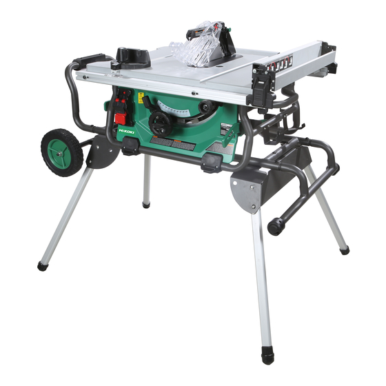
Page 8: Overview
English OVERVIEW... - Page 9 English Blade guard Blade wrench Stand support assembly Push stick Narrow fence Outfeed support Scale Handle II Rip fence lock lever Riving knife Mitre gauge Lock knob Adjusting knob Rear rail Table insert Working table Handle I Rip fence Saw blade Front fence rail Adjustable foot Blade guard storage...
-
Page 10: Specifications
English SPECIFICATIONS Input Voltage 230-240V~, 50Hz Power Input 1500W No Load Speed 4500/min Blade Size ø254mm × ø30mm × 2.8mm, 40T Bevel Range 0°~45° Working Table Size 730mm x 559mm Outfeed Support Size 730mm x 50mm Max. cutting depth at 0° 79mm Max. -
Page 11: Loose Parts
English LOOSE PARTS The following items are included with your table saw: PART DESCRIPTION QUANTITY Table saw assembly Mitre gauge (in stored position) Blade guard assembly (in stored position) Anti-kickback pawls assembly (in stored position) Outfeed support assembly Rip fence assembly (in stored position) Push stick (in stored position) Stand support assembly Wheel shaft... -
Page 12: Assembly
English ASSEMBLY UNPACKING YOUR TABLE SAW This product requires assembly. ◌ Carefully lift saw from the carton and place it on a level work surface. ◌ Inspect the tool carefully to make sure that no breakage or damage occurred during shipping. ◌... - Page 13 English ◌ Slide one wheel (12), one big flat washer 10 (55) and one lock nut M10 (56) onto the wheel shaft (57), secure wheel in place by tightening the lock nut M10. Repeat with the second wheel. (Fig. 1c) ◌...
- Page 14 English ◌ Grasp the handle I (5) firmly and slowly tilt saw downward until the saw is balanced on the ground. (Fig. 2b-2c) ◌ Grasp the stand support assembly (26) and lift it up until two other stand legs (11) leaving off the ground, then fold out two stand legs (11).
- Page 15 English TO REMOVE/REPLACE/ALIGN THE TABLE INSERT (Fig. 4a-4b) WARINING: The table insert must be level with the saw table. If the table insert is too high or too low, the workpiece can catch on the uneven edges, resulting in binding or kickback, which could result in serious personal injury. WARINING: Be care of your hands avoided to be striked with the saw blade which could result in serious personal injury when removing or reinstalling the table insert.
- Page 16 English REMOVING AND INSTALLING THE BLADE (Fig. 6a-6b) CAUTION: Check the arbor hole diameter of the blade before installing the blade. Always use the correct ring for the arbor hole of the blade you intend to use. CAUTION: To work properly, the saw blade teeth must point down toward the front of the saw. Failure to heed this instruction could cause damage to the saw blade, the saw or the workpiece.
- Page 17 English ◌ Pull out and hold knob (67). Align slot in anti-kickback pawls (48) over the slot A (68) indicated of riving knife (16). Place the spring pin (69) on the anti-kickback pawls (48) into the slot (A) (68) indicated on the riving knife (16). ◌...
- Page 18 English OUTFEED SUPPORT ASSEMBLY INSTALLATION (Fig. 9a-9b) ◌ Loosen and remove two stop screws (78) on the extension poles (79) of the outfeed support (15). ◌ Loosen the locking knobs (80) under the working table counterclockwise. ◌ Insert the rear extension poles (79) into the two holes in the rear of the working table and into the extension tube brackets that are located under the working table.
- Page 19 English Fig. 10c MITRE GAUGE INSTALLATION (Fig. 11a-11b) The mitre gauge (28) can be installed on each mitre gauge groove (31) on either side of blade. ◌ Remove the mitre gauge (28) from mitre gauge storage (47) located on inside of the right side of saw. ◌...
- Page 20 English FOLDING THE STAND (Fig. 13a-13f) ◌ To fold the stand for moving, return fence rails and lock the fence rails lock lever and return outfeed support to inner position. Store the accessories securely. ◌ Grasp the stand support assembly (26) and lift it up until two stand legs (11) (located on side of the wheel) leaving off the ground, then fold in two stand legs (11).
- Page 21 English CONNECT TO A DUST COLLECTION SYSTEM (Fig. 14) The dust extraction port (33) with 63.5 mm size is located on the back of the table saw. This port can be connected directly to a dust collection system by connecting the pick up end of the dust collection hose to the dust port. WARINING: ALWAYS connect to a dust collection system and the table saw must be regularly checked for dust built up and cleaned frequently, otherwise there is a risk of heat built up and potential fire.
-
Page 22: Operation
English OPERATION WARINING: To reduce the risk of serious personal injury, turn unit off and unplug the tool before making any adjustments or removing/ installing attachments or accessories. An accidental start-up can cause injury. WARINING: Before using the saw, verify the following each and every time: •... - Page 23 English Kickback may propel the workpiece at high velocity towards anyone standing in front and in line with the saw blade. • Never reach over or in back of the saw blade to pull or to support the workpiece. Accidental contact with the saw blade may occur or kickback may drag your fingers into the saw blade.
- Page 24 English CHANGING BLADE ANGLE (BEVEL) (Fig. 17) CAUTION: A 90° cut has a 0° bevel and a 45° cut has a 45° bevel. CAUTION: If bevel indicator is not at zero when saw blade is at 0°, see the section “Adjusting bevel indicator” (Page 30). ◌...
- Page 25 English MITRE GAUGE (Fig. 19) The mitre gauge (28) provides accuracy in angled cuts. For very close tolerances, test cut are recommended. There are two mitre gauge grooves, one on either side of blade. When making a 90° cross cut, use either mitre gauge groove. When making a beveled cross cut (blade tilted in relation to working table, mitre gauge should be located in groove on right so that blade is tilted away from mitre gauge and hands.
- Page 26 English CUTTING TIPS ◌ The kerf (the cut made by the blade in the wood) will be wider than the blade to avoid overheating or binding. Make allowance for the kerf when measuring wood. ◌ Make sure the kerf is made on the waste side of the measuring line. ◌...
- Page 27 English MAKING A MITRE CUT (Fig. 25) ◌ Remove rip fence. ◌ Set blade to correct depth for workpiece. ◌ Set mitre gauge (28) to the desired angle and tighten lock knob (44). ◌ Make sure the wood is clear of the blade before turning on the saw. ◌...
- Page 28 English MAKING A COMPOUND (BEVEL) MITRE CUT (Fig. 28) ◌ Remove rip fence. ◌ Unlock bevel lock lever. ◌ Adjust bevel angle to desired setting. ◌ Lock bevel lock lever. ◌ Set blade to correct depth for workpiece. ◌ Set mitre gauge (28) to desired angle and tighten lock knob (44). ◌...
-
Page 29: Adjustments
English ADJUSTMENTS WARNING: Before performing any adjustment, make sure tool is unplugged from power supply and switch is in off position. Failure to do so could result in serious personal injury. WARNING: Make sure the blade guard is reinstalled immediately after making any adjustment which requires it to be removed. Failure to heed this instruction could result in serious personal injury. - Page 30 English ◌ Remove the anti-kickback pawls and blade guard. ◌ Using a triangle square (93), set the blade (30) to exactly 45°. ◌ If the blade stops bevelling before it gets to 45°, loosen the 45° stop set screw (93) (located at the right of the bevel track on the front), and then adjust it to 45°. ◌...
-
Page 31: Maintenance
(other than routine maintenance) must be performed by an HiKOKI Authorized Service Center ONLY. NOTE: Specifications are subject to change without any obligation on the part of HiKOKI. STORAGE After operation of the tool has been completed, check that the following has been performed: ◌... -
Page 32: Troubleshooing
The accessories of this machine are listed on page 11 (Refer to “LOOSE PARTS” chapter ). CAUTION: Repair, modification and inspection of HiKOKI Power Tools must be carried out by a HiKOKI Authorized Service Center. In the operation and maintenance of power tools, the safety regulations and standards prescribed in Australia must be observed. - Page 33 English Hikoki Power Tools Australia Pty. Ltd. Unit 1, 10 Boden Road, Seven Hills, NSW 2147, Australia Code No. C99739611 Printed in China...
Need help?
Do you have a question about the C 10RJ and is the answer not in the manual?
Questions and answers
5/8 inch dado set, current blade is 30mm bore & fits on back flange.is a new fling required to fit the dado's 5/8 inch bore??