
Related Manuals for HIKOKI C 12LCH


Summary of Contents for HIKOKI C 12LCH
- Page 1 复合式斜口锯 Compound Miter Saw C 12LCH C 12FCH • 保留备用 Keep for future reference 使用说明书 Handling instructions...
-
Page 2: Table Of Contents
中文 目次 作业上的一般注意事项.......2 打开包装.............7 使用复合锯须知..........3 作业之前.............7 符号...............5 使用前调节电动工具........8 部件名称.............5 实际应用.............9 规格...............6 锯条的安装和拆卸........17 标准附件.............7 维护和检查.............19 选购件 (另售) ...........7 维修零部件一览表........21 用途...............7 作业上的一般注意事项 警告! 当使用电动工具时,为了减少造成火灾、电击和人身伤害,必须时刻遵守基本 注意事项,以及下述操作注意事项。 在操作本机之前,请通读本说明书,并予以妥善保管。 安全操作注意事项∶ 1. 工作场所应打扫干净,清理妥当,杂乱无章将导致事故。 2. 确保妥适的作业环境。电动工具不可任其风吹雨打。不得在潮湿的地方作业。 工作场所需保持充分的亮度。 请勿在有可能造成火灾或爆炸的地方使用电动工具。 3. 谨防触电事故。应避免身体同大地或接地表面接触不可让访客触摸电动工具 或延伸线缆 (例如∶管道、散热器、炉灶、冰箱等)。 4. 不可让孩童和体弱人士靠近工作场所。请勿让访客触摸工具或延伸线缆。与 作业无关的访客也必须保持安全距离。 5. 不使用的电动工具应存放到干燥而孩童和体弱人士伸手不及的高处,并加锁 保管。... -
Page 3: 使用复合锯须知
中文 12. 作业以安全第一为原则。工件要用夹具或台钳卡紧。这样做,比用手按压更 为可靠,也能够让双手专心操作。 13. 作业时脚步要站稳,身体姿势要保持平衡。 14. 工具应维护妥善,经常保持锋利、清洁才能充分发挥性能,落实作业安全的 要求。应按规定加注润滑脂、更换附件。线缆应定期检查,如发现损伤应即 委托专业性的服务单位加以修复。延伸电缆如有损伤应予更换。手柄要保持 干燥,并防止沾附油脂类。 15. 不使用时、维修前以及更换附件 (如∶刀具、钻头、锯具等) 之前,都必须 拆卸电源插头才行。 16. 开动前务必把调整用键和扳手类拆除下来。这一点与安全有关。应养成习惯, 严格遵守。 17. 谨防误开动。插头一插上电源插座,指头就不可随便接触电源开关。插接电 源之前,应先确认∶开关是否切断。 18. 室外延伸线缆的使用。室外作业时,必须使用专用的延伸线缆。 19. 保持高度警觉,充分掌握情况,以正常的判断力从事作业。疲惫时切不可开 动电动工具。 20. 检查损坏部件。在继续使用电动工具之前,应详细检查各部零件以及防护装 置有无损坏,以便判断工具能否正常工作、能否发挥正常效能。检查转动部 份的对准、空转、各零件有无异常、安装是否妥善以及其它足以给工作带来 不良影响的情况。如防护以及其它零件损伤了。除非本说明书中已有记载否 则应即委托服务中心进行妥善修理或更换。开关一发现缺陷,应即委托服务 中心加以更换。如开关不能正常地接通或切断,绝不可使用该电动工具。 21. 警告 使用非本说明书中的推荐的附件可能有发生人身损害的危险。 22. 本工具必须委托有资格的维修人员进行维修。 本电动工具满足相关的安全要求。 维修必须由专业人员使用纯正配件来进行。 否则有可能会给用户造成人身损害。... - Page 4 中文 8. 不可使用溶剂擦拭塑料零件。因为∶汽油、冲淡剂、轻质汽油、四氯化碳、 酒精等都会使塑料损伤或发生龟裂,所以应避免使用。擦拭塑料制品,可以 使用稍微沾湿了肥皂水的柔布。 9. 只能使用HiKOKI指定的更换零件。 10. 本电动工具只在更换炭刷时才可拆解。 11. 本使用说明书中的组装分解图仅用于经授权的维修店。 12. 切勿切割铁金属或砖瓦材料。 13. 提供充足的总体或局部照明。原料与成品工件应位于操作员的正常工作位置 附近。 14. 必要时应使用适当的个人保护设备,可包括 : 听力保护,以减少听力受损的风险。 眼部保护,以减少眼睛受伤的风险。 呼吸保护,以减少吸入有害灰尘的风险。 手套,用于操作锯条 (移动锯条时应尽可能把锯条放在支架中) 以及粗糙材料。 15. 操作员应接受机器使用、调节与操作方面的充分培训。 16. 在机器运行且锯头未处于停止位置时,不得从切割区域移去工件的任何切片 或其他部分。 17. 复合锯的下护罩锁定在开启位置时,切勿使用复合锯。 18. 确保下护罩能够平滑地移动。 19. 安全罩未处于正常位置时请勿使用复合锯,要在其工作状态良好且得到正确 的维护的情况下使用。 20. 使用经过正确磨快的锯条。注意锯条上标注的最大速度。 21. 锯条破损或变形时请勿使用。...
-
Page 5: 部件名称
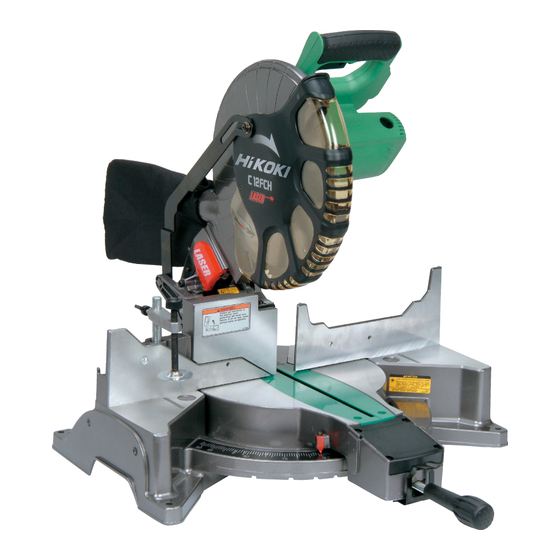
中文 39. 务必考虑切割操作中所有可能产生的遗留风险,如激光辐射对眼睛的伤害、 无意中接触机器滑动机械部分的运动部件等等。 符号 警告! 如下所示的符号用于本机。使用前请务必理解其含意。 为降低伤害风险,用户必须阅读使用说明书 部件名称 电动头 手柄 齿轮箱 防尘袋 电动机 锯片 下护罩 激光标记器 挡板 (A) 虎钳组件 导板 挡板 (B) 数字显示器 (仅 C12LCH 有) 连杆 小挡板 侧手柄 回转台 指针 (A) (用于斜接尺) 图 1 开关 (用于激光标记器) 开关 铭牌 开关... - Page 6 中文 规格 63.5 mm×200 mm 0° 或 98 mm×155 mm 最大切割容量 斜接 45° 63.5 mm×140 mm 高 × 宽 斜角左 45° 42 mm×200 mm 复合 (斜角左 45°, 42 mm×140 mm 斜接 45°) 锯条尺寸 (外径×内径×厚度) 305 mm×25.4mm×2.7 mm 斜接切割角 右与左 0° ~ 52° 斜面切割角...
-
Page 7: 标准附件
中文 标准附件 除了主机 (1 台) 外,产品包中还包括表中所列的附件。 305 mm TCT 锯条 (安装在工具上) 防尘袋 17 mm 套筒扳手 虎钳组件 4 mm 六角条形扳手 选购件 (另售) (1) 扩展支架和止动片 (2) 冠状模塑虎钳组件 (包括冠状模塑止动片(左)) (3) 冠状模塑止动片 (左) (4) 冠状模塑止动片 (右) 用途 ○ 切割各种类型的铝制框架和木材。 打开包装 ○ 请小心打开电动工具和所有相关物品 (标准附件) 的包装。 ○... -
Page 8: 使用前调节电动工具
中文 2. 电源开关 确认电源开关是否切断。若电源开关接通,则插头插入电源插座时电动工具 将出其不意地立刻转动,从而招致严重事故。 3. 延伸线缆 若作业场所移到离开电源的地点,应使用容量足够、铠装合适的延伸线缆, 并且要尽可能地短些。 4. 当准备运输电动工具时,其主要部件须用锁 手柄 定插销固定 稍稍移动手柄,可使锁定插销脱落。 在 运 输 过 程 中 , 将 锁 定 插 销 锁 在 齿 轮 箱 内 (图 3)。 拉 5. 将防尘袋安装在电动工具上 (第 5 页的图 1) 插销... -
Page 9: 实际应用
中文 实际应用 警告! 警告标志 警告标志 直线 直线 ○ 为避免人员受伤,使用工具时切 勿从台上移走工件或把工件放在 台上。 ○ 使用工具时切勿使四肢进入警告 图 5 标志旁边的线内,否则可能发生 危险 (见图 5)。 注意! ○ 在锯条转动时取下或安装工件非 常危险。 ○ 在进行切割作业时,请从回转台 上清除刨花。 ○ 如果刨花堆积太多,切割材料的 锯条便会暴露。切勿让您的手或 6 mm 螺栓 支架 (B) 其他任何东西靠近暴露的锯条。 图 6 1. 用虎钳组件紧紧固定要切割的材 料,使其在切割中不会移动 螺栓支架... - Page 10 中文 注意! 须确保虎钳降低进行切割时不会与电动头接触。如果有可能碰到,请松开 6 mm 翼栓 (B) 并将虎钳组件移到不会碰到锯片的位置。 小挡板 5. 确认使用副挡板 (图 8) 这个电动工具配备有副挡板。在 直接角度切割中,请使用副挡板, 这样就可以实现对具有宽大背面 的材料进行稳定的切割。在左斜 挡板 (B) 角切割中,请将副挡板升高,如 图 8 所示,然后逆时针旋转。 图 8 警告! 在左斜角切割中,请逆时针旋转副挡板 (图 8)。如果不是逆时针旋转,主体 或锯条可能与副挡板接触,从而引起伤害。 6. 使用墨线 在降低电动机部分时,下护罩升起,而出现锯条。 将墨线与锯条对齐。 注意! 在锯条旋转时切勿提起下护罩。 不仅会接触副挡板并影响切割精度,还可能损坏安全罩。 开关 (用于激光标记器) 7. 激光线的位置调节 可以方便地在本工具上画墨线以...
- Page 11 中文 (2) 然后把 4 mm 六角条形扳手插入齿 4 mm 六角 轮箱侧面的 12 直径孔中,转动六角 条形扳手 套筒固定螺丝以移动激光线。(如顺 时针转动六角套筒螺丝,激光线将 激光线 向右侧移动,如逆时针转动,激光 线将向左侧移动。 ) 如使用时墨线与 锯条的左侧对齐,则将激光线与凹 槽的左端对齐 (图 10)。如墨线与锯 条的右侧对齐,则将激光线与凹槽 凹槽 的右侧对齐。 图 10 (3) 调节激光线的位置之后,在工件上 画出一条直角墨线,并将墨线与激光线对齐。对齐墨线时,应一点一点地滑 动工件, 并在激光线与墨线重叠的位置将其用虎钳固定。再次进行凹槽操作, 并检查激光线的位置。如需改变激光线的位置,则按照第 (1) 至 (3) 步再次 进行调节。 警告!(图...
- Page 12 中文 ○ 在室外或靠近窗户的操作中, 可能由于日光的原因而难以 激光线 看清激光线。此时应移至不直 接暴露于日光的地点,并进行 操作。 ○ 不要拖动电动头后方的电线 或用手指、木头等钩住,否则 标志 (预先标记) 电线可能脱落,使激光标记器 图 13 不能点亮。 ○ 定期检查并确认激光线的位置 是否正确。检查方法:在工件 斜接角度 斜角角度 上画出一条直角墨线,其高度 窗口 窗口 约 38 mm、宽度约 89 mm, 并检查激光线是否与墨线对 斜接角度 斜角角度 齐 [墨线与激光线之间的偏离 复位按钮 复位按钮 应小于墨线的宽度 (0.5 mm)] (图13)。...
- Page 13 中文 (2) 如果显示器上的数字与前挡板 角度仍然不匹配,则使回转台 回到 0° 位置。然后松开侧手柄, 左右移动回转台, 如图 16 所示。 在将回转台设置在正确位置 0° 斜接角度 之后,再按复位按钮。 复位按钮 注 : ○ 开始切割前,请将电动工具与斜接 侧手柄 角度 (0°) 和斜角角度 (0°) 对准,并 图 16 按住它们的复位按钮至少 0.2 秒。 如果在没有将电动工具对准到 0° 时按下数字显示器的开关,则数字显示器 上显示的数字与电动工具角度将不匹配。 ○ 如果数字显示器开关关闭,激光标记器将不会亮起。(仅 C12LCH 有) ○ 请勿在会产生电气噪声的设备,如发电机等附近使用电动工具。电气噪声可 能引起数字显示器读数或操作错误。...
- Page 14 中文 10. 斜接切割程序 (1) 松开侧手柄,并推动角度止动片 的连杆。然后调节回转台,直至 指针与斜接尺上的所需设定对齐 回转台 斜接尺 (图 18)。 指针 (A) (2) 重新拧紧侧手柄,确保回转台处 连杆 (用于斜接尺) 于所需位置。 注 : 侧手柄 ○ 在 0° 中 心 设 定 的 右 侧 与 左 侧, 图 18 15°、22.5°、31.6° 与 45° 设定的 位置,回转台均会停止转动。...
- Page 15 中文 12. 斜角角度微调 (图 20 与图 21) 手柄 (1) 握紧电动头上的手柄,将它定位 在所需的斜角角度。临时紧固夹 紧杆。 旋钮 (A) 注意! 如果紧固得不够牢,电动头可能 突然移动或滑落,从而引起伤害。 图 20 请务必牢牢地紧固电动头,使它 旋钮 (A) 不会移动。 (2) 握紧手柄并移动旋钮 (A),对斜角 夹紧杆 角度进行微调。 注 : 板 (A) 顺时针转动旋钮 (A) 将使电动工 具向左微调 (从前方看)。 板 (B) 逆时针转动旋钮 (A) 将使电动工 图...
- Page 16 中文 14. 安装支架 (选购件) 6 mm 翼栓 在切割操作中,支架可用于延长工 (选购件) 支架 件台并使之保持正确位置。 方钢 (选购件) (1) 如图 22 所示,使用方钢来对齐支架 的上缘与底座面。松开 6 mm 翼状 螺母。旋转高度调节螺栓 6 mm,并 调节支架的高度。 6 mm (2) 调节后,旋紧翼状螺母并用6 mm旋 翼状螺母 钮螺栓 (选购件) 固定支架。如高度 高度调节螺栓 底座面 (选购件) 调节螺栓6 mm 的长度不足,则在其 6 mm (选购件) 下方放置一块薄板。高度调节螺栓...
-
Page 17: 锯条的安装和拆卸
中文 (2) 冠状模塑虎钳 (B) (选购件) 可 冠状模塑虎钳组件 (左) (选购件) 6 mm 安装在左挡板 (挡板 (B)) 或右 旋钮 旋钮螺栓 挡板 (挡板 (A)) 上。它可与冠 状模塑的斜角结合,并可按下 虎钳。 挡板 (B) 然后按照需要转动上部旋钮, 以可靠地连接冠状模塑。如需 6 mm 升高或降低虎钳组件,首先应 冠状模塑 翼栓 (A) 松开 6 mm 翼栓。 冠状模塑止动片 (左) 调节高度后,旋紧6 mm翼栓, (选购件) 然后按照需要旋转上部旋钮,... - Page 18 中文 1. 安装锯条 (图 26,图 27 与图 28) 主轴锁 (1) 旋转下护罩 (塑料) 至上部位置。 (2) 按下主轴锁并用 17 mm 套筒扳手 (标准件) 松开螺栓。 由于螺栓为左侧螺纹,需向右旋转 将其松开,如图 27 所示。 注 : 如难以按下主轴锁以锁定主轴,则 图 26 在于主轴锁上施加压力的同时用 17 mm套筒扳手 (标准件) 转动螺 17 mm 螺栓 栓。 套筒扳手 向内按下主轴锁时,锯条主轴被锁 垫圈...
-
Page 19: 维护和检查
中文 维护和检查 警告! 为了避免发生事故和人体伤害,在对本电动工具进行任何维修和检查之前, 必须先确认已关闭开关及已从电源插座拔下电源插头。 1. 检查锯条 连杆 发现变质或损坏后应立即更换锯条。 六角头螺栓 损坏的锯条可引起人身伤害,而磨损的 锯条则可导致无效的操作,并可能使电 动机过载。 注意! 切勿使用不锋利的锯条。锯条不锋利时, 图 29 它对于由工具手柄所施加的手部压力的 锯片 阻力会增加,使电动工具的使用变得不 挡板 (B) 安全。 2. 检查连杆 (图 29 与图 30) 如 M8 六角头螺栓 (2) 松动,用方钢对齐 挡板与锯条的侧面。将锯条与挡板调整 至 90 度角后,旋紧连杆以固定六角头 方钢 螺栓 (2)。 图... - Page 20 (1) 开关处于关闭 (OFF) 位置。 (2) 电源插座从插座中拔出。 不使用工具时,将其储藏在儿童无法接触的干燥场所。 8. 润滑油 每月应润滑以下滑动面一次,以使电动工具长时间保持良好的工作状态 (第 5 页的图 1 与第 5 页的图 2)。 请使用推荐的机油。 注油位置∶ * 回转支架的转动部分 * 虎钳组件的转动部分 9. 清洁 定期用蘸有肥皂水的湿布除去电动工具表面上 (尤其是下护罩内) 的碎屑、 灰尘以及其他废料。为了避免电动机发生故障,切勿使其接触油或水。 如由于碎屑等粘在激光标记器发光部分的窗口上而无法看清激光线,则用干 布或以肥皂水等蘸湿的软布擦拭并清洁窗口。 10. 维修零部件一览表 注意! HiKOKI牌电动工具的修理、更改与检查必须由取得HiKOKI授权的维修中心 进行。 特别是激光装置必须由取得激光制造商授权的代理商进行维护。 务必把激光装置的修理交由HiKOKI授权的维修中心进行。 在要求修理或其他维护服务时,最好把本零件清单与工具一同交付HiKOKI授 权的维修中心。 在电动工具的操作与维护中,务必遵守各个国家的安全规定与标准。...
-
Page 21: 维修零部件一览表
中文 维修零部件一览表 C12LCH (1/3) 1 15 12 13 14 13 24 25 33 34 26 27 36 37 29 30 61 62 70 71... - Page 22 中文 项目号 代码号 使用数 备注 项目号 代码号 使用数 备注 323-141 323-684 323-137 302-518 “44” 323-138 984-528 949-900 D3 × 14 323-601 “47-49” 323-142 990-541 M5 × 16 962-782 M5 × 6 323-602 949-531 D2 × 12 322-963 323-144 949-214 M4 × 6 975-144 949-431 323-139...
- Page 23 中文 C12LCH (2/3) 122 123 124 134 173 125 130 601 621...
- Page 24 中文 项目号 代码号 使用数 备注 项目号 代码号 使用数 备注 323-658 380MM 322-954 993-539 M4 × 16 311-144 973-313 304-043 M4 × 10 304-043 M4 × 10 323-631 993-539 M4 × 16 323-630 “147” 323-650 – – –– –– – –– – – 323-624 301-806 M6 ×...
- Page 25 中文 项目号 代码号 使用数 备注 321-549 949-313 949-556 322-047 949-425 323-681 M6 × 105 974-561 949-404 M6X × 20 323-545 “601,621” 322-957 “622-628” 321-551 M10 × 54 998-836 M6 × 11 – – –– – –– – –– – 306-985 964-851 304-043 M4 ×...
- Page 26 中文 C12LCH (3/3) 203 204...
- Page 27 中文 项目号 代码号 使用数 备注 项目号 代码号 使用数 备注 988-101 323-675 323-652 307-028 D4 × 25 – – – – – – – – – – – – – – – – – 305MM-D25.4- 323-632 984-750 D4 × 16 NT120 937-631 323-651 –...
- Page 28 中文 C12FCH (1/3) 1 15 12 13 14 13 24 25 28 29 61 62...
- Page 29 中文 项目号 代码号 使用数 备注 项目号 代码号 使用数 备注 323-141 949-431 323-137 949-454 323-138 949-821 M5 × 16 949-900 D3 × 14 323-664 “54” 323-142 949-900 D3 × 14 962-782 M5 × 6 949-660 M6 × 20 949-531 D2 × 12 323-683 323-144 949-221...
- Page 30 中文 C12FCH (2/3) 122 123 124 118 119 159 160 601 621...
- Page 31 中文 项目号 代码号 使用数 备注 项目号 代码号 使用数 备注 949-216 M4 × 10 – – – – – – – – – – – – – – – – – 954-878 M4 × 16 323-692 323-650 323-546 “602-605” 323-624 301-806 M6 ×...
- Page 32 中文 C12FCH (3/3) 203 204...
- Page 33 中文 项目号 代码号 使用数 备注 项目号 代码号 使用数 备注 988-101 949-431 323-652 323-675 – – – – – – – – – – – – – – – – – 305MM- 307-028 D4 × 25 984-750 D4 × 16 D25.4-NT120 937-631 323-651 –...
-
Page 34: General Operational Precautions
English CONTENTS GENERAL OPERATIONAL PRECAUTIONS ..........34 PRECAUTIONS ON USING COMPOUND MITER SAW ......36 SYMBOL ....................... 37 NAME OF PARTS..................38 SPECIFICATIONS ..................39 STANDARD ACCESSORIES ............... 39 OPTIONAL ACCESSORIES (sold separately)..........40 APPLICATION ....................40 UNPACKING ....................40 PRIOR TO OPERATION ................ - Page 35 English 10. Connect dust extraction equipment. Cutting operation by this compound miter saw may produce considerable amount of dust from extraction duct on fi xed guard. (Dust material: Wood or Aluminium) If devices are provided for the connection of dust extraction and collection facilities ensure these are connected and properly used.
-
Page 36: Precautions On Using Compound Miter Saw
Clean plastic parts with a soft cloth lightly dampened with soapy water. Use only original HiKOKI replacement parts. 10. This tool should only be disassembled for replacement of carbon brushes. 11. The exploded assembly drawing on this handling instructions should be used only for authorized service facility. -
Page 37: Symbol
English 22. Do not use saw blades manufactured from high speed steel. 23. Use only saw blades recommended by HiKOKI. 24. The saw blades should be from 290 mm to 305 mm external diameter ranges. 25. Select the correct saw blade for the material to be cut. -
Page 38: Name Of Parts
English NAME OF PARTS Motor Head Handle Gear Case Dust Bag Motor Saw Blade Lower Guard Laser Marker Fence (A) Vise Assembly Table Insert Fence (B) Digital display (Only C12LCH) Lever Sub Fence Side Handle Turntable Indicator (A) (For miter scale) Fig. -
Page 39: Specifications
English SPECIFICATIONS 63.5 mm × 200 mm 0° Max. Cutting 98 mm × 155 mm Capacity Miter 45° 63.5 mm × 140 mm Height × Width Bevel Left 45° 42 mm × 200 mm Compound (Bevel Left 45°, Miter 45°) 42 mm ×... -
Page 40: Optional Accessories (Sold Separately)
English OPTIONAL ACCESSORIES (sold separately) Extension Holder and Stopper Crown molding Vise Ass’y (Include Crown molding Stopper (L)) Crown molding Stopper (L) Crown molding Stopper (R) APPLICATION Cutting various types of aluminium sash and wood. ○ UNPACKING Carefully unpack the power tool and all related items (standard accessories). ○... -
Page 41: Adjusting The Power Tool Prior To Use
English During bevel and compound cutting, attach the dust bag at a right angle to the base surface as shown in Dust Bag Fig. 4. CAUTION Empty the dust bag frequently to prevent the duct and the lower guard from becoming clogged. Duct Sawdust will accumulate more quickly than Base... - Page 42 English Holder (B) adjustment (Fig. 6) Loosen the 6 mm bolt with the supplied 10 mm box wrench. Adjust the holder (B) until its bottom surface contacts the bench or the fl oor surface. Using the Vise Assembly (Standard accessory) (Fig.
- Page 43 English CAUTION Never lift the lower guard while the saw blade is rotating. The sub fence will not only make contact and adversely aff ect cutting accuracy, this could also result in damage to the guard. Position adjustment of laser line Switch Ink lining can be easily made on this tool to the (For laser marker)
- Page 44 English WARNING (Fig. 11 and Fig. 12) Make sure before plugging the power ○ plug into the receptacle that the main body and the laser marker are turned Fig. 11 off . Exercise utmost caution in handling ○ a switch trigger for the position adjustment of the laser line, as the power plug is plugged into the receptacle during operation.
- Page 45 English Digital display panel (for C12LCH) (Fig. 14 and Fig. 15) Miter angle Bevel angle Turning on the digital display window window switch shows 0° for both miter and bevel angle, regardless of main unit angle. Miter angle Bevel angle Align the main unit angle with the reset button reset button...
- Page 46 English Do not use the main unit near equipment that generates electrical noise such as ○ generators. Electrical noise might cause faulty readings or operation on the digital display. Cutting operation As shown in Fig. 17 the width of the saw blade is the width of the cut.
- Page 47 English Re-tighten the side handle to secure the turntable in the desired position. NOTE Positive stops are provided at the right and left of the 0° center setting, at 15°, 22.5°, 31.6° ○ and 45° settings. Check that the miter scale and the tip of the indicator are properly aligned. Operation of the saw with the miter scale and indicator out of alignment, or with the side ○...
- Page 48 English CAUTION If not tightened fi rmly enough the motor head might suddenly move or slip, causing injuries. Be sure to tighten the motor head section enough so it will not move. Make fi ne adjustments to the bevel angle by gripping the handle and moving the knob (A). NOTE Turning knob (A) clockwise, allows fi...
- Page 49 English After adjustment, fi rmly tighten Stopper (Optional accessory) Workpiece the wing nut and fasten the holder with the 6 mm knob bolt Holder (Optional accessory) (optional accessory). If the length of Height Adjustment Bolt 6 mm is insuffi cient, spread a thin plate 6 mm Wing Nut beneath.
-
Page 50: Mounting And Dismounting Saw Blade
English The crown molding vise (B) (Optional Crown Molding Vise Ass’y (L) accessory) can be mounted on either (Optional accessory) 6 mm the left fence (Fence (B)) or the right Knob Bolt fence (Fence (A)). lt can unite with the Knob slope of the crown molding and vice can be pressed down. - Page 51 English Mounting the saw blade (Fig. 26, Fig. 27 and Spindle Lock Fig. 28) Rotate the lower guard (plastic) to the top position. Press in spindle lock and loosen bolt with 17 mm box wrench (standard accessory). Since the bolt is left-hand threaded, loosen by turning it to the right as show in Fig.
-
Page 52: Maintenance And Inspection
English CAUTION Never attempt to install saw blades except 290 mm – 305 mm in diameter. MAINTENANCE AND INSPECTION WARNING To avoid an accident or personal injury, always confi rm the trigger switch is turned OFF and that the power plug has been disconnected from the receptacle before performing any maintenance or inspection of this tool. - Page 53 English About Handling the Motor (see Fig. 1 on page 38) Winding of the motor is said to be the heart of this tool. Exercise utmost caution not to damage the winding by exposing it to wash oil or water. NOTE Accumulation of dust and the like inside the motor can result in a malfunction.
- Page 54 Always assign the repair of laser device to HiKOKI Authorised Service Center. This Parts List will be helpful if presented with the tool to the HiKOKI Authorized Service Center when requesting repair or other maintenance. In the operation and maintenance of power tools, the safety regulations and...
-
Page 55: Service Parts List
English SERVICE PARTS LIST C12LCH (1/3) 1 15 12 13 14 13 24 25 33 34 26 27 36 37 29 30 61 62 70 71... - Page 56 English Item Item Code No. Remarks Code No. Remarks Used Used 323-141 323-595 323-137 323-684 323-138 302-518 “44” 949-900 D3 × 14 984-528 323-142 323-601 “47-49” 962-782 M5 × 6 990-541 M5 × 16 949-531 D2 × 12 323-602 323-144 322-963 975-144 949-214...
- Page 57 English C12LCH (2/3) 122 123 124 134 173 125 130 601 621...
- Page 58 English Item Item Code No. Remarks Code No. Remarks Used Used 101 323-658 380MM 141 949-216 M4 × 10 102 993-539 M4 × 16 142 322-954 103 973-313 143 311-144 104 304-043 M4 × 10 144 304-043 M4 × 10 105 993-539 M4 ×...
- Page 59 English Item Code No. Remarks Used 610 301-806 M6 × 15 611 323-657 “612-617” 612 321-549 613 949-313 614 949-556 615 322-047 616 949-425 617 323-681 M6 × 105 618 974-561 619 949-404 M6X × 20 620 323-545 “601,621” 621 322-957 “622-628”...
- Page 60 English C12LCH (3/3) 203 204...
- Page 61 English Item Item Code No. Remarks Code No. Remarks Used Used 988-101 307-028 D4 × 25 323-632 323-652 – – – – – – – – – – – – – – – – – 305MM-D25.4-NT120 984-750 D4 × 16 323-651 937-631 323-208...
- Page 62 English C12FCH (1/3) 1 15 12 13 14 13 24 25 28 29 61 62...
- Page 63 English Item Item Code No. Remarks Code No. Remarks Used Used 323-141 949-214 M4 × 6 323-137 949-431 323-138 949-454 949-900 D3 × 14 949-821 M5 × 16 323-142 323-664 “54” 962-782 M5 × 6 949-900 D3 × 14 949-531 D2 ×...
- Page 64 English C12FCH (2/3) 122 123 124 118 119 159 160 601 621...
- Page 65 English Item Item Code No. Remarks Code No. Remarks Used Used 949-216 M4 × 10 323-626 954-878 M4 × 16 – – – – – – – – – – – – – – – – – 323-650 323-692 323-624 323-546 “602-605”...
- Page 66 English C12FCH (3/3) 203 204...
- Page 67 English Item Item Code No. Remarks Code No. Remarks Used Used 988-101 323-675 323-652 307-028 D4 × 25 – – – – – – – – – – – – – – – – – 305MM-D25.4-NT120 984-750 D4 × 16 323-651 937-631 323-208...
- Page 68 服务中心 工机商业(中国)有限公司 上海市闵行区浦江工业园区三鲁路3585号7幢3楼 制造商 福建高壹工机有限公司 福建省福州市福兴投资区湖塘路 编号:C99132724 F 发行日期:2018年6月 中国印刷...
Need help?
Do you have a question about the C 12LCH and is the answer not in the manual?
Questions and answers