Advertisement
Quick Links
Download this manual
See also:
User Manual
Advertisement

Related Manuals for HIKOKI C 10FSH


Summary of Contents for HIKOKI C 10FSH
-
Page 1: Handling Instructions
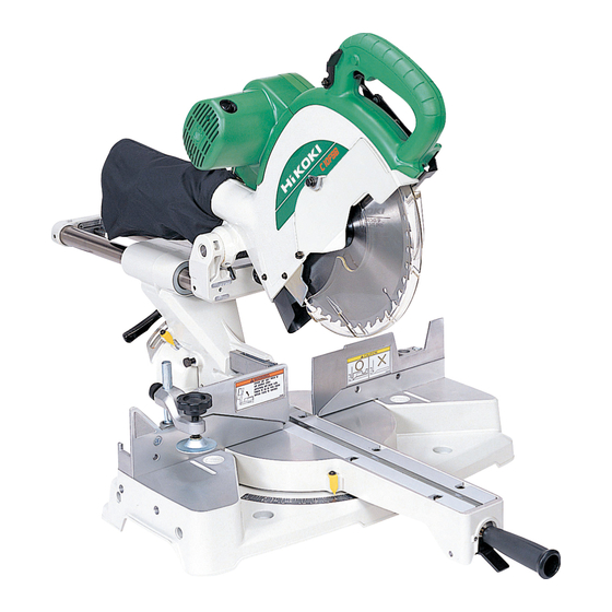
Slide Compound Miter Saw C 10FSH C 10FSB • Handling instructions Readthroughcarefullyandunderstandtheseinstructionsbeforeuse. - Page 2 §...
- Page 3 LASER RADIATION Do not show in the laser line. (laser beam) LASER CLASS Po<3mW, C6=3, (lambda)=654nm, Time basis 0.25s DIN EN 60825-1:2001-11 C417607...
- Page 4 å † ç £ ç † 6 mm 17 mm ¢...
- Page 5 English 한국어 Handle 핸들 Lever (A) 레버(A) Motor Head 모터 헤드 Gear Case 기어 케이스 Motor 모터 Dust Bag 분진 주머니 Hinge 힌지 Holder (A) 홀더(A) Sub Cover 하위 커버 Indicator (For right bevel scale) 표시등(우측 베벨 눈금용) Laser Marker (Only C10FSH) 레이저...
- Page 6 English 한국어 Workpiece 작업물 8 mm Hexagon Socket Set Screw 8 mm 육각 소켓 세트 스크루 8 mm Depth Adjustment Bolt 8 mm 깊이 조정 볼트 8 mm Wing Nut 8 mm 윙 너트 6 mm Knob Bolt (Optional accessory) 6 mm 노브...
-
Page 7: General Operational Precautions
14. Maintain tools with care. Keep cutting tools sharp a soft cloth lightly dampened with soapy water. and clean for better and safer performance. Follow Use only original HiKOKI replacement parts. instructions for lubrication and changing This tool should only be disassembled for accessories. -
Page 8: Specifications
37. Shut off power and wait for saw blade to stop before 23. Use only saw blades recommended by HiKOKI. servicing or adjusting tool. Use of saw blade comply with EN847-1. 38. During a miter or bevel cut the blade should not be 24. - Page 9 English STANDARD ACCESSORIES ADJUSTING THE POWER TOOL PRIOR TO USE (1) 262 mm TCT Saw blade (mounted on tool) ....1 CAUTION (2) Dust bag ..............1 Make all necessary adjustments before inserting the (3) 10 mm Box wrench ............ 1 plug in the power source.
- Page 10 English After placing a suitable wooden piece to sit on the Remove the workpiece and securely tighten the 6 mm fence and the table surfaces, fix it with the vise. After center machine screw. Adjust the right hand table the switch has been turned on and the saw blade has insert in the same way.
- Page 11 English (1) Light up the laser marker and make a groove of about 5 (2) Once the saw blade contacts the workpiece, push the mm deep on the workpiece that is about 20 mm in height handle down gradually to cut into the workpiece. and 150 mm in width.
- Page 12 English CAUTION 16. Bevel cutting procedures CAUTION When transporting or carrying the tool, do not grasp Ensure that the clamp lever is securely fixed when the holder. beveling. There is the danger of the holder slipping out of the Please do this if the length of the material being cut base.
-
Page 13: Maintenance And Inspection
English NOTE In this case turn the switch off immediately and raise the When cutting a single groove at either end of the handle to its initial position. Then turn the switch on and workpiece, remove the unneeded portion with a after running the tool for 20 seconds without a load for chisel. - Page 14 C : No. Used D : Remarks CAUTION Repair, modification and inspection of HiKOKI Power Tools must be carried out by a HiKOKI Authorized Service Center. Especially laser device should be maintained by the authorised agent by laser manufacturer. Always assign the repair of laser device to HiKOKI Authorised Service Center.
- Page 15 H i K OK I...
- Page 16 H i KOK I...
- Page 17 ○ 절단용 톱 헤드를 내리려면, 레버(A)를 엄지손가락으로 기본 부속품 눌러 잠금장치를 해제해야 합니다. (1) 레버(A)를 누른 상태에서 핸들을 내리 누를 때, 하부 (1) 262 mm TCT 톱날(공구에 장착) ....... 1 보호장치가 부드럽게 회전하는지 확인하십시오(그림 5). (2) 분진 주머니 ..........1 (2) 다음으로, 핸들을...
- Page 18 6. 바이스 어셈블리 사용(기본 부속품)(그림 12) 를 고정하십시오. 그런 다음, 뒷면이 넓은 작업물을 바이스 어셈블리는 좌측 펜스(펜스 (B)) 또는 우측 펜스 안정적으로 절단할 수 있습니다. 경고 (펜스 (A))에 장착할 수 있으며 작업물의 높이에 따라 올리거나 내릴 수 있습니다. 바이스 어셈블리를 올리거나 우측...
- Page 19 ○ 분해하지 마십시오. 원할 경우, 절단 각도 대신에 마이터 눈금을 설정하는 데 ○ 레이저 마커에 강한 충격을 주지 마십시오(공구 본체). 사용될 수 있습니다. 강한 충격을 주면 레이저선의 위치가 어긋나게 되어 (5) 따라서 작업물을 2/10 기울기로 절단하려면 표시기를 레이저 마커가 손상되고 사용 수명이 줄어듭니다. 정위치로...
- Page 20 주의 톱날 장착 및 제거 ○ 공구를 운반하거나 갖고 다닐 때, 홀더를 잡지 마십시오. ○ 홀더가 베이스에서 미끄러져나올 위험이 있습니다. 홀더 경고 대신에 핸들을 잡으십시오. 사고 또는 상해를 방지하려면, 톱날을 제거하거나 20. 정밀 절단용 스토퍼 … (스토퍼와 홀더는 옵션 부속품) 설치하기...
- Page 21 HiKOKI HiKOKI HiKOKI HiKOKI H i K OK I...
- Page 22 C10FSH...
- Page 23 C10FSH...
- Page 24 C10FSH...
- Page 25 C10FSH 305-180 949-429 305-179 949-215 M4 × 8 312-488 321-349 ”89” 329-409 332-814 ”105” 965-077 996-276 321-330 321-332 949-429 961-554 M8 × 10 949-215 M4 × 8 302-518 ”80” 320-141 984-528 303-409 M8 × 25 319-270 321-370 ”14-20” 949-312 308-396 949-633 M8 ×...
- Page 26 C10FSH 321-550 949-555 305-558 D5 × 25 988-821 321-355 307-732 151 1 321-354 110V-120V –––––––– 151 2 322-200 220V-240V 322-454 930-804 M4.0 312-492 321-380 322-884 ”160” 301-653 D4 × 20 321-398 6201VVCMNS7S 880-734 M5 × 25 976-819 319-503 322-456 321-383 302-757 980-063 935-196...
- Page 27 C10FSB...
- Page 28 C10FSB...
- Page 29 C10FSB...
- Page 30 C10FSB 305-180 949-215 M4 × 8 305-179 332-817 ”89” 312-488 996-276 329-409 321-332 965-077 961-554 M8 × 10 321-330 302-518 ”79” 949-429 984-528 949-215 M4 × 8 949-312 320-141 949-633 M8 × 50 303-409 M8 × 25 320-141 321-370 ”14-20” 949-237 M5 ×...
- Page 31 C10FSB 322-207 ”134, 146” –––––––– 930-703 306-985 149 1 340-779C 110V ”148” 964-851 149 2 340-779F 230V-240V ”148” 304-043 M4 × 10 953-174 D5 × 55 960-017 M6 × 32 321-399 608VVC2NS7L 301-806 M6 × 15 152 1 360-898U 110V-120V ”151, 196” ––––––––...
- Page 32 Hitachi Koki Co., Ltd. Code No. C99115052 F Printed in China...
Need help?
Do you have a question about the C 10FSH and is the answer not in the manual?
Questions and answers