Advertisement
Quick Links
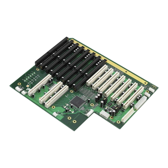
PCA-6114P7 Backplane: 14-slot BP for 15-slot Chassis, 4 ISA, 6
PCI, 3 PICMG, 1 ISA/PCI
Startup Manual
Packing List
Before you begin installing your card, please make sure that
the following items have been shipped:
1. PCA-6114P7 startup manual
2. 3-pin ATX connector cable
3. Screw M4*6L (15 pcs)
4. 2-year quality warranty card
If any of these items are missing or damaged, please con-
tact your distributor or sales representative immediately.
Note:
Acrobat Reader is required to view any PDF
file.Acrobat Reader can be downloaded at:
www.adobe.com/Products/acrobat/readstep2.
html (Acrobat is a trademark of Adobe)
Specifications
Standard Functions
• PICMG 1.0 slots: PCA-6114P7 supports PICMG 1.0 CPU
boards
• ISA slots: Four ISA slots
• 32-bit PCI: Six 32 bit/33 MHz PCI slots
• PCI/ISA slot: One PCI/ISA slot
Mechanical and Environment
• Dimension: 335.01 mm x 259.99 mm
• Power supply voltage: +12 V, +5 V, -12 V, -5 V, +3.3 V,
+5 VSB
• Power requirements: Refer to the CPU board, add-on
card, and peripherals
• Operating temperature: 0 ~ 60° C
• Weight: 0.87 kg
For more information on this and other Advantech
products, please visit our website at:
http://www.advantech.com
http://www.advantech.com/eplatform
For technical support and service, please visit our
support website at:
http://support.advantech.com
This manual is for the PCA-6114P7 Series.
Part No. 2002611472
Printed in China
2002611472
1700030500
1939000410
2190000902
3rd Edition
May 2014
Jumpers and Connectors
The board has a number of jumpers that allow you to con-
figure your system to suit your application. The table below
lists the function of each of the jumpers and connectors.
Jumpers and Connectors
Connectors
Label
PICMG1, PICMG2,
PICMG3
ISA1, ISA4, ISA6~ISA8
ISA2, ISA3, ISA5
PPCI1~PPCI3
SPCI4~SPCI7
VKB1, VKB3
HKB2
VAT1
VBTX1
HBIG1
HCN1
HCN2
HCN3
Jumpers
Label
HCN1
1
2
3
Remove default jumper
and connect 3-pin ATX
connector cable
J1
3
6
9
1
4
7
PCA-6114P7 Startup Manual 1
Function
PICMG1.0 CPU board slot
16-bit ISA bus connector
PICMG connector (ISA slot in
PICMG1, PICMG2, PICMG3)
32 bit / 33MHz PCI slot
32 bit / 33MHz PCI slot
Keyboard-Out, from CPU card
K/B connector
Keyboard-in, 5-pin external
K/B connector
AT power connector
ATX power connector
Big 4-pin power connector
PS-On, to CPU card for ATX
power signal
Alarm board power connector
+5V and +12V fan connector
Function
ATX/AT Mode Selection
AT Mode
ATX Mode
PCI Bridge Voltage Selection
Setting 5V voltage to PCI slot
(default)
Advertisement

Related Manuals for Advantech PCA-6114P7


Summary of Contents for Advantech PCA-6114P7
- Page 1 PCA-6114P7 Backplane: 14-slot BP for 15-slot Chassis, 4 ISA, 6 PCI, 3 PICMG, 1 ISA/PCI Startup Manual Packing List Jumpers and Connectors The board has a number of jumpers that allow you to con- Before you begin installing your card, please make sure that the following items have been shipped: figure your system to suit your application.
-
Page 2: Jumpers And Connectors
Setting 3.3V voltage to PCI slot KB_VCC MSCLK VBTX1 VAT1 Name Name 3.3V 3.3V -12V Power OK 5VSB 3.3V 3.3V -12V HCN1 Name PSON PSON 5VSB HCN2 Name 5VSB HBIG1 Name +3.3V -12V HCN3 Name VKB1, VKB3 Name 2 PCA-6114P7 Startup Manual... -
Page 3: Board Diagram
AD29 INTD INTA INTB INTC KBDAT SPCI1 SAD20 INTA INTB INTC INTD MSDAT SPCI2 SAD21 INTB INTC INTD INTA KB_GND SPCI3 SAD22 INTC INTD INTA INTB KB_VCC SPCI4 SAD23 INTD INTA INTB INTC MSCLK Board Diagram PCA-6114P7 Startup Manual 3... - Page 4 PPCI3 SPCI2 SPCI4 VKB1 VKB3 VBTX1 VAT1 HBIG1 HCN2 HKB2 HCN3 HCN1 PICMG2 PICMG3 PICMG1 Note: When a PCI card and ISA card are inserted in PPCI1 and ISA1, those cards may conflict with each other. 4 PCA-6114P7 Startup Manual...
-
Page 5: Board Dimensions
Board Dimensions PCA-6114P7 Startup Manual 5...
Need help?
Do you have a question about the PCA-6114P7 and is the answer not in the manual?
Questions and answers