Table of Contents
Advertisement
Quick Links
Advertisement
Table of Contents

Related Manuals for Trojan GLIDE CYCLE 510


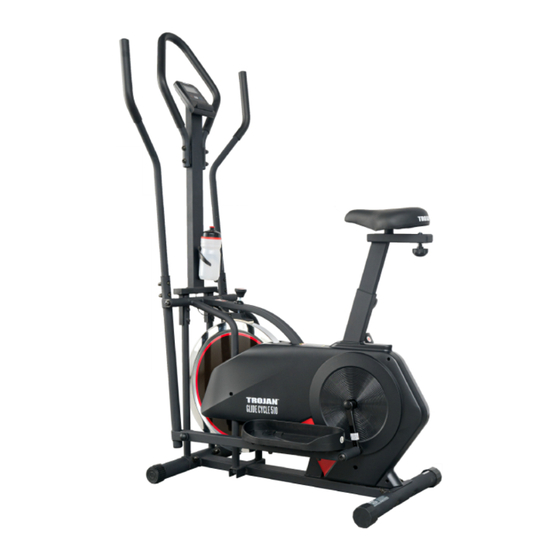
Summary of Contents for Trojan GLIDE CYCLE 510
-
Page 2: Table Of Contents
INDEX • Important Safety Instructions ________________________________ 3 • Pre Assembly Check List ______________________________________ 5 • Hardware & Tools List ________________________________________ 6 • Parts List ____________________________________________________ 7 • Exploded Drawing ___________________________________________ 9 • Assembly Steps ______________________________________________ 10 • Console Functions ___________________________________________ 14 •... -
Page 3: Important Safety Instructions
IMPORTANT SAFETY INSTRUCTIONS It is the sole responsibility of the purchaser of Trojan products to read the owner’s manual, warning labels and instruct all individuals, on proper usage of the equipment. Understanding each and every warning to the fullest is important. If any of these instructions or warnings are unclear please contact Trojan Customer Services on 0861 TROJAN (0861 876526), within the Republic of South Africa. - Page 4 INSPECTION • Do not use or permit use of any equipment that is damaged, or has worn or broken parts. For all Trojan equipment use only replacement parts supplied by Trojan. • Always make sure that all nuts and bolts are tightened prior to each use.
-
Page 5: Pre Assembly Check List
PRE ASSEMBLY CHECK LIST Thank you for choosing the Glide Cycle 510 Elliptical. We take great pride in producing this product and hope it will provide many hours of quality exercise to make you feel better, look better and enjoy life to its fullest. Yes, it’s a proven fact that a regular exercise program can improve your physical and mental health. -
Page 6: Hardware & Tools List
HARDWARE & TOOLS LIST INSTRUCTIONS FOR ASSEMBLY • Before you start to assemble, please check the hardware packaging to make sure all parts are included. • Basic tools, such as spanners will be provided for assembly. -
Page 7: Parts List
PARTS LIST Description Description 1 pair Main Frame Crank (L/R) Front Bottom Tube Plastic Cap Back Bottom Tube Axle Right Coupler Bar Snap spring Bearing Left Coupler Bar Nut (M10 x 1.25 mm) Right Pedal Tube Left Pedal Tube End cap Right Handle Bar Chain (80Z) End Cap... - Page 8 PARTS LIST Description Description D Shape Washer (M28 × 16.2 x 14 x B5”) Handlebar Post Nut (M6) Bolt (M10 × 18 mm) Plastic Roller Bearing 6000 Bolt (M6 X 48 mm) Nut (M6) Bolt (M5 Open-End Wrench S13-S14-S15 Handlebar Grip Bolt (M10 ×...
-
Page 9: Exploded Drawing
EXPLODED DRAWING... -
Page 10: Assembly Steps
ASSEMBLY STEPS 1. PREPARATION • Before assembling make sure that you will have enough space around the item. • Use the supplied parts and hardware for the assembly. • Before assembling please check whether all the required parts have been supplied as per the exploded drawing on the opposite page. - Page 11 ASSEMBLY STEPS STEP 3: PEDALS ASSEMBLY STEP 3 Attach the Pedals (11L) (11R) to the Pedal tubes (6L) (6R) with Bolts (M10 x 50) (44) Washer (φ16 x φ8 x 2.0) (77) and Nylon nuts (M8) (66). STEP 4: HANDLEBAR ASSEMBLY STEP 4 Insert the Handlebar (7L, 7R) to the Coupler Bar (5, 4), select a height setting that is comfortable to...
- Page 12 Insert the Vertical Seat post (67) onto the Main Frame (1). Secure it with Spring Knob (70). To select which height you want, remove Washer (77) and Nylon Nut (66) from Seat, then Tighten Seat (64) with Washer (65) and Nylon Nut (66). Slide the Seat Post (68) into the vertical Seat Post (67) and at the desired position, align the holes and fix in place with the Locking Knob (17) and Washer (D20) (77)
- Page 13 ASSEMBLY STEPS STEP 7 STEP 7: CONSOLE Attach the Handlebar (100) to the Support Tube (79) with Screws (M10 x 130) (10), Arc Washer (D10) (49), Washer (D10) (21) and Nut (M10) (47). Attach the Console (50) to the Support Tube (79) with the Bolt (M5 x 10) (83). Connect the Middle Wire (75) to the Sensor Wire (37).
-
Page 14: Console Functions
CONSOLE FUNCTIONS SPECIFICATIONS: TIME (TMR) 00:00 - 99:59 SPEED (SPD) 0.0 - 99.9 KM/H or MI/H DISTANCE (DST) 0.00 - 999.9 KM AUTO SCAN Every 5 seconds TOTAL DISTANCE (ODO) 0.00 - 999.9 KM or MI/H CALORIES 0.0-9999 Kcal FUNCTION BUTTON: MODE: This key lets you to select a particular function you want. - Page 15 CONSOLE FUNCTIONS CALORIES: (1) Counts the total calories of the exercise from start to end. (2) Press the “MODE” button until “CAL” appears, Press the “SET” button to set the exercise calories. When the “SET” shows zero, the computer will send an alarm for 10 seconds. ODO: The total distance which this function is refers to from battery capacity period runs.
-
Page 16: Exercise Instructions
EXERCISE INSTRUCTIONS Using your Glide Cycle 510 Elliptical provides you with several benefits, it will improve physical fitness, tone muscle and in conjunction with a calorie controlled diet, help you lose weight. THE WARM UP PHASE the risk of cramp and muscle injury. It is advisable to do a few stretching exercises as shown below. Each stretch should be held for approximately 30 seconds, do not force or jerk your muscles into a stretch. - Page 17 MUSCLE TONING To tone muscle while on your Glide Cycle 510 Elliptical you will need to have the resistance set quite high. This will put more strain on your leg muscles and may mean you cannot train for as long as you would like. If normal during the warm up and cool down phases, but towards the end of the exercise phase you should increase resistance, making your legs work harden than normal.
-
Page 18: Maintenance
MAINTENANCE CLEANING The Glide Cycle 510 Elliptical can be cleaned with a soft cloth and mild detergent. Do not use abrasives or solvents on plastic parts. Please wipe your perspiration off the Glide Cycle 510 Elliptical after each use. Please inspect all assembly bolts and pedals on the machine for proper tightness before use. -
Page 19: Fitness Tips & Techniques
Always consult your physician before beginning any exercise program. MUSCLE CHART The exercise routine that is performed on the Glide Cycle 510 Elliptical will develop the whole body muscle group as well as condition the circulatory system and provide a good aerobic workout. These muscle groups are highlighted on the muscle chart below. -
Page 20: Conditioning Guidelines
CONDITIONING GUIDELINES How you begin your exercise program depends on your physical condition. If you have been inactive for several years, or are severely overweight, you must start slowly and increase your time on the equipment, a few minutes per workout. Initially, you may be able to exercise only for a few minutes in your target zone, however, your aerobic to work at your own pace. -
Page 21: Warm Up & Cool Down
WARM UP & COOL DOWN WORKOUT GUIDELINES Each workout should include the following 3 parts: 1. A WARM-UP: 5 to 10 minutes of stretching and light exercise. A proper warm-up increases your body temperature, heart rate, and circulation in preparation for exercise. 2. -
Page 22: Year Limited Warranty
Consumer upon collection or delivery of the repaired product. The Consumer does not need to return the product to the store. The Consumer should call the Trojan Call Centre on 0861 Trojan (0861 876526). Customers residing outside South Africa can contact us on +27 10 206 4405 and the call centre will advise of the procedure. -
Page 23: Repairs Procedure
Do not return the product to the store. Call the Trojan Call Centre on 0861 Trojan (0861 876526) to log the faulty product (under warranty or out of warranty). Customers residing outside South Africa can contact us on +27 10 206 4405.
Need help?
Do you have a question about the GLIDE CYCLE 510 and is the answer not in the manual?
Questions and answers