Advertisement
Table of Contents
- 1 Elliptical Trainer
- 2 Table of Contents
- 3 Safety Instructions
- 4 Pre Assembly Check List
- 5 Hardware List
- 6 Assembly Steps
- 7 Computer Functions
- 8 Fitness Tips & Techniques
- 9 Conditioning Guidelines
- 10 Warm-Up and Cool-Down
- 11 Frequently Asked Questions
- 12 Parts List
- 13 Exploded Drawing
- 14 Trojan 1 Year Warranty
- 15 Trojan Repairs Procedure
- Download this manual
Advertisement
Table of Contents

Related Manuals for Trojan IMAGE 350


Summary of Contents for Trojan IMAGE 350
-
Page 1: Elliptical Trainer
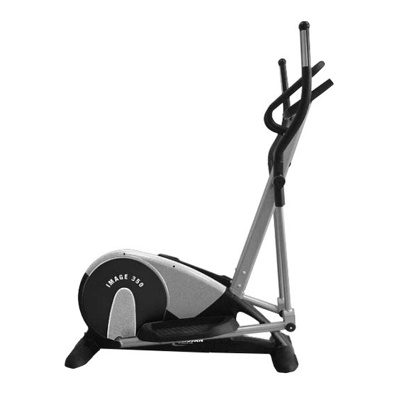
TROJAN ® IMAGE 350 MY SPACE MY TIME ELLIPTICAL TRAINER IMAGE 350 CARE INSTRUCTION AND ASSEMBLY MANUAL CAUTION READ ALL PRECAUTIONS AND INSTRUCTIONS IN THIS MANUAL BEFORE USING THIS EQUIPMENT KEEP THIS MANUAL FOR FUTURE REFERENCE 0861 876526 0861 TROJAN WARRANTY www.trojanhealth.co.za... -
Page 2: Table Of Contents
PRE ASSEMBLY CHECK LIST HARDWARE LIST ASSEMBLY STEPS COMPUTER FUNCTIONS FITNESS TIPS & TECHNIQUES CONDITIONING GUIDELINES 8 . WARM -UP AND COOL-DOWN FREQUENTLY ASKED QUESTIONS 10. PARTS LIST 11. EXPLODED DRAWING 12. TROJAN 1 YEAR WARRANTY 13. TROJAN REPAIRS PROCEDURE... -
Page 3: Safety Instructions
1. SAFETY INSTRUCTIONS It is the sole responsibility of the purchaser of TROJAN products to read the owner’s manual, warning labels and instruct all individuals, on proper usage of the equipment. Understanding each and every warning to the fullest is important. If any of these instructions or warnings are unclear please contact Trojan Customer Services on 0861 876 526 (0861 Trojan), within the Republic of South Africa. - Page 4 SAFETY INSTRUCTIONS INSPECTION • Do not use or permit use of any equipment that is damaged or has worn or broken parts. For all TROJAN equipment use only replacement parts supplied by TROJAN. • Always make sure that all nuts and bolts are tightened prior to each use.
-
Page 5: Pre Assembly Check List
2. PRE ASSEMBLY CHECK LIST Thank you for choosing the TROJAN IMAGE 350.We take great pride in producing this quality product and hope it will provide many hours of quality exercise to make you feel better, look better and enjoy life to its fullest. -
Page 6: Hardware List
3. HARDWARE LIST 10169-6... - Page 7 HARDWARE LIST DESCRIPTION QUANTITY 1/29R&L/2 Main Frame with Chain Cover, Pedal Tube Weld 1 set 7/46/48/12/9/19 Front Post/Axle Decolation/Washer/Screw/ Hand Pulse Wire 1 set 3R&L/27/28/24/25R&L Upper Handle Bar (R&L) with Foam Grip ,End Cap, Hand Pulse Wire, Hand Pulse 1 set Bottom Handle Bar 11/51 Monitor with Sensor Wire, 4 Screws...
-
Page 8: Assembly Steps
4. ASSEMBLY STEPS Instructions for assembly • Unpack the carton and using the parts list check that all parts are accounted for. • Do not dispose of the packaging material until assembly is completed. • An Allen Wrench is provided for use in assembly. STEP 1 •... - Page 9 ASSEMBLY STEPS STEP 3 • Attach the Left Upper Swing Bar (3L) to the Left Lower Handlebar (4) and secure with 2 Nuts (42), and 2 Hex Head Bolts (41). • Repeat the same procedure for Right Swing Bar (3R) and the Right Lower Handlebar (4) connection.
- Page 10 ASSEMBLY STEPS STEP 6 • Apply a small amount of grease to Pedal Tube Axle (39). A second person must hold the Left Pedal Tube (2L) inside the bracket on the Left Lower Handlebar (4). Insert the Pedal Tube Axle (39) through Lower Handlebar (4) and the Pedal Tube (2L).
-
Page 11: Computer Functions
5. COMPUTER FUNCTIONS 7 DISPLAY FUNCTIONS: TIME: Displays the exercise time 00:00 - 99:59 (Count up) or 99.59 - 00:00 (Count down). SPEED: Displays the current speed in kph (0.00-99.9 KPH / MPH). RPM: Displays the number of pedal revolutions per minute. DISTANCE: Displays the distance covered (0.00-99.9 Kilometers /Miles). - Page 12 COMPUTER FUNCTIONS LCD DISPLAY UNIT This system provides 12 different Exercise Programs.When you preset the workout time, the system will divide the time into 10 regular intervals, which will become your Exercise Time Segments. If you do not preset your intended workout time, the system program will count up the workout time in one-second increments.
-
Page 13: Fitness Tips & Techniques
6. FITNESS TIPS AND TECHNIQUES AEROBIC EXERCISE Aerobic exercise is any sustained activity that sends oxygen to your muscles via your heart and lungs. Aerobic exercise improves the fitness of your lungs and heart - your body’s most important muscle. Aerobic exercise fitness is promoted by any activity that uses your large muscles (arms, legs, or buttock, for example). -
Page 14: Conditioning Guidelines
7. CONDITIONING GUIDELINES How you begin your exercise program depends on your physical condition. If you have been inactive for several years, or are severely overweight, you must start slowly and increase your time on the equipment; a few minutes per workout. Initially, you may be able to exercise only for a few minutes in your target zone, however, your aerobic fitness will improve over the next six to eight weeks. -
Page 15: Warm-Up And Cool-Down
8. WARM-UP AND COOL-DOWN WORKOUT GUIDELINES Each workout should include the following three parts: A warm-up, consisting of 5 to 10 minutes of stretching and light exercise. A proper warm-up increases your body tem- perature, heart rate, and circulation in preparation for exercise. Training zone exercise, consisting of 20 to 30 minutes of exercising with your heart rate in your training zone. -
Page 16: Frequently Asked Questions
9. FREQUENTLY ASKED QUESTIONS – IMAGE 350 1. The consol is showing the incorrect reading. • Check that the connector on the back of the consol is plugged in correctly. • Check the batteries in the consol are inserted in the correct orientation and that they are in working condition • Press the reset button to test if the error has corrected itself. 2. The functions are not working properly or display incorrectly. • Check that the connector on the back of the consol is plugged in correctly. • Press the reset button to test if the error has corrected itself. 3. There is no pulse reading or the data displayed is unstable. -
Page 17: Parts List
10. PARTS LIST Q’TY Description Q’TY Description Main Frame Ø12.5 Protect Cable Plug 2R/L 1Pair Pedal Tube Weld Ø32 x 460 x 5.0mm Foam Grip 3R/L 1Pair Upper Handlebar Weld Ø50 x Ø29 Ball Cap Bottom Handlebar Weld 29R/L 1Pair Chain Cover Left Crank Bracket M4 x 25mm Machine Screw... - Page 18 PARTS LIST Q’TY Description Q’TY Description M5 x 12mm Across Head Screw Motor Bracket M5 x 15mm Machine Screw Motor M5 x 10mm Screw M5 x 12mm Screw M8 x 1.25P x 74mm Axle Transportation Wheel Ø16 x Ø10.3 x 4.8mm Spacer Adjustable Washer M8*1.25P x 18mm Adjustable Knob 6200Z Bearing M5 x 20mm Machine Screw...
-
Page 19: Exploded Drawing
11. EXPLODED DRAWING 10169-19... -
Page 20: Trojan 1 Year Warranty
12. TROJAN 1 YEAR WARRANTY The Manufacturer hereby provides a warranty to the original purchaser of this product (‘the Consumer’) that this product will be free of manufacturing defects in materials and workmanship which under normal, personal, family or household use (commercial use expressly excluded) manifest themselves within the 1 year from the date of purchase. - Page 21 Consumer upon collection or delivery of the repaired product. The Consumer does not need to return the product to the store. The Consumer shall phone the Trojan hotline on 0861 Trojan (0861 876 526) and the Manufacturer’s authorized agent will at its discretion either repair the item at the Consumer’s residence or collect and repair the item at their premises.
-
Page 22: Trojan Repairs Procedure
13. TROJAN REPAIRS PROCEDURE 1. Procedure for repairs Should you experience any faults or breakdowns on your Trojan equipment, please adhere to the following procedure to have the fault rectified speedily and professionally. • Do not return the product to the store* Call 0861 Trojan (0861 876526) to log the faulty product (under warranty or out of warranty) • • The operator or technical advisor will try identify the fault, and will book a service team call out. • The service team will endeavour to fix the problem in your home on an agreed date and time.
Need help?
Do you have a question about the IMAGE 350 and is the answer not in the manual?
Questions and answers
How to open the battery cover? How to switch om the machine? Where can you buy another AP adapter if that is where the problem lies?