Table of Contents
Advertisement
Quick Links
Advertisement
Table of Contents

Related Manuals for THORLABS BNT001/IR


Summary of Contents for THORLABS BNT001/IR
- Page 1 BNT001/IR ® Benchtop NanoTrak Controller User Guide Original Instructions...
-
Page 2: Table Of Contents
Contents Chapter 1 Overview ..................1 1.1 Description ..................... 1 1.2 Software ....................1 1.3 PC Software Overview ................2 1.3.1 Introduction ......................2 1.3.2 Kinesis Server ....................2 1.3.3 Software Upgrades ..................... 3 Chapter 2 Safety ..................... 4 2.1 Safety Information .................. 4 2.2 General Warnings .................. - Page 3 4.3.1 Safety Testing ....................34 4.3.2 Cleaning ......................34 Appendices Appendix A Troubleshooting ..............35 Appendix B Specifications and Associated Parts ........36 Appendix C Principles of Operation ............38 Appendix D Regulatory ................43 Appendix E Thorlabs Worldwide Contacts ..........45...
-
Page 4: Chapter 1 Overview
See Section 1.3. for a full description of the Kinesis software. The key innovation of the Thorlabs range of controllers and associated mechanical products is the ease and speed with which complete automated alignment systems can be engineered at both the hardware and software level. -
Page 5: Pc Software Overview
1.3 PC Software Overview 1.3.1 Introduction The BNT001 NanoTrak controllers feature USB connectivity (allowing multiple units to be used together on a single PC), fully featured Graphical User Interface (GUI) panels, and extensive software function libraries for custom application development. The Kinesis software suite provides a flexible and powerful PC based control system both for users of the equipment, and software programmers aiming to automate its operation. -
Page 6: Software Upgrades
This is available either by pressing the F1 key when running the Kinesis server, or via the Start menu, Start\Programs\Thorlabs\Kinesis\Kinesis Help. 1.3.3 Software Upgrades Thorlabs operate a policy of continuous product development and may issue software upgrades as necessary. HA0114T Rev 10 May 2019... -
Page 7: Chapter 2 Safety
To minimize the possibility of this happening it is strongly recommended that any such modes that result in prolonged unresponsiveness be disabled before the software is run. Please consult your system administrator or contact Thorlabs technical support for more details. -
Page 8: Chapter 3 Set Up And Operation
Chapter 3 Chapter 3 Set Up And Operation 3.1 Introduction The functionality required for a client application to control a number of NanoTrak units is provided by the NanoTrak Control Object within the APT server, with manual operation being facilitated via a GUI panel (see Section 3.7.1.). Instances of this ActiveX control can be dragged from the toolbox in the development software. -
Page 9: Front Panel Controls And Indicators
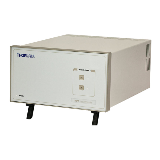
NanoTrak Autoalignment Controller 3.2 Front Panel Controls and Indicators CHANNEL ENABLE Power NanoTrak Controller Fig. 3.1 Front panel controls and indicators Power LED – Indicates that power is applied to the unit. Channel 1 and Channel 2 buttons – Used to enable/disable channel functionality. The associated LED is lit when the channel is enabled. -
Page 10: Detector Heads And Cables
A range of connectors are available which simply plug into the connector on the rear panel. The BNT001/IR NanoTrak is supplied with an Infra Red InGaAs photodiode, and a standard SMB connector for use with external detector heads which incorporate a PIN (p-type/intrinsic/n-type) diode. -
Page 11: Installing The Software
If you experience any problems when installing software, contact Thorlabs on +44 (0)1353 654440 and ask for Technical Support. DO NOT CONNECT THE CONTROLLER TO YOUR PC YET 1) Go to Services/Downloads at www.thorlabs.com and download the Kinesis... - Page 12 2) Run the software and check that the Graphical User Interface (GUI) panel appears and is active. Fig. 3.3 Gui panel showing jog and ident buttons 3) Click the ‘Identify’ button. The digital display of the associated channel on the front panel of the controller flashes.
-
Page 13: Manual Operation - Nanotrak
NanoTrak Autoalignment Controller 3.7 Manual Operation - NanoTrak 3.7.1 Description of GUI Panel Controls Fig. 3.4 NanoTrak Software GUI... - Page 14 Chapter 3 Note The serial number of the unit associated with the GUI control instance is displayed in the top right hand corner of the control. Range indicator - displays the current range of the internal power meter. When operating in 'Manual' ranging mode, the range can be changed by clicking the required range number.
- Page 15 NanoTrak Autoalignment Controller respectively. This setting is provided as a convenient way of smoothing readings displayed on the GUI only, and does not affect in any way those same readings when returned by software functions. To change the setting, click the associated sector. Relative Signal Power Bar - The max power located in the alignment.
- Page 16 Chapter 3 'Settings' list. Note. Use of this control will automatically switch the circle diameter adjustment mode to 'Manual'. Settings list - shows user specified settings for the parameters listed below. Note. Some parameters can also be configured for automatic adjustment. When operating in the relevant 'Auto' mode, the user specified values displayed may be different to the actual values applied (and in some cases, displayed on the CRT).
-
Page 17: Circle Position Window
NanoTrak Autoalignment Controller 3.8 Circle Position Window Right click in the Circle Position Display, to show the position window. This window shows the current circle position in whatever display units are selected, NanoTrak units or Microns. The circle can be positioned by entering a value into the X and/or Y fields and clicking the arrow. -
Page 18: Settings Panel
Chapter 3 3.9 Settings Panel When the 'Settings' button on the GUI panel is clicked, the 'Settings' window is displayed. This panel allows data such as scan circle frequency and diameter, and loop gain to be entered. Note that all of these parameters have programmable equivalents accessible through the functions on this Control (refer to the Kinesis API helpfile for further details. - Page 19 NanoTrak Autoalignment Controller If the Diameter Mode is set to 'LUT', the circle diameter is adjusted automatically, using a table of range dependent circle diameter values (in NanoTrak units). When automatic LUT diameter adjustment mode is enabled, the system uses values in this LUT to modify circle diameter in relation to the input range currently selected.
- Page 20 Chapter 3 When in closed-loop mode, position is maintained by a feedback signal from the piezo actuator strain gauge or by a DC feedback signal derived externally. Note. This is only possible when using actuators equipped with position sensing. Channel Outputs - these parameters allow the horizontal and vertical channels of the NanoTrak to be enabled/disabled.
-
Page 21: Input/Output Tab
NanoTrak Autoalignment Controller 3.9.2 Input/Output tab Fig. 3.6 NanoTrak Settings panel - Input/Output Tab Input Signal Signal Source - the input source can be set to PIN or a range of BNC voltage inputs. The PIN Input option should be used when NanoTraking to optimise a PIN current feedback signal. - Page 22 Chapter 3 If dB is selected, readings are displayed or returned in decibels. The signal is first converted to watts according to the calibration factor specified in the A/W Calibration parameter, and then into dB. A/W Calibration - the Amp:Watt calibration factor used when Watts or dBs is specified in the PIN Units Mode parameter.
- Page 23 NanoTrak Autoalignment Controller rises above the limit specified in the ‘Upper’ parameter, the unit increments the range to the next higher setting. Settings are entered as a percentage of full range. Note The Upper limit must be higher than the Lower limit. If an attempt is made to enter a value for the Lower limit which is higher than the Upper limit, an error message is generated.
-
Page 24: Display Tab
Chapter 3 3.9.3 Display tab Fig. 3.7 NanoTrak Settings panel - NanoTrak Screen Tab Sometimes, it may be useful to explore the area of interest by manually repositioning the two piezos driven by the NanoTrak. If desired, the NanoTrak circle can be positioned by using the mouse. This feature allows manual repositioning of the piezos, e.g. - Page 25 NanoTrak Autoalignment Controller Note This setting affects only the NanoTrak screen and not the main 'Settings' display. If no piezo actuators are connected, then Microns cannot be selected and the display can only show NT units. Horizontal and Vertical Increments - When the circle is positioned by a mouse click, the incremental distance can be set to NT units or microns.
-
Page 26: Hv Settings Tab
Chapter 3 3.9.4 HV Settings Tab Fig. 3.9 NanoTrak Settings panel - HV Amps tab This panel is used to set the output characteristics of the HV amplifier channels fitted to the NanoTrak unit. Both low pass filtering and current control settings can be made to tailor the piezo output drive to a particular application. -
Page 27: Programmed Operation - Nanotrak
Legacy AC (Strain Gauge) - The AC Strain Gauge mode refers to the use of AC excited strain gauge feedback signals as generated by the complete range of Thorlabs piezo actuators and piezo equipped multi axis stages. Differential DC - It is possible to set the feedback signal type to DC 0 – 10V. This configures the feedback circuit to accept a differential 0-10V DC feedback signal in order to control position output. -
Page 28: Using An External Power Meter
Chapter 3 Note If the circle reaches the edge of the display, this means that the piezo actuators cannot move far enough to reach the position of maximum power. The horizontal and vertical actuators should be adjusted to bring the circle away from the edge of the screen –... -
Page 29: Using Two Nanotraks In The Same System
NanoTrak Autoalignment Controller 3.10.3 Using Two NanoTraks in the Same System The NanoTrak scanning process uses a single frequency (and a highly selective discriminator similar to a radio receiver) and it is possible to use more than one NanoTrak controller in a single optical path (and with a single detector). For example, with two control units set to different scanning frequencies (e.g.30 Hz and 40 Hz) it is possible to couple fibers both into (master NanoTrak) and out of (slave NanoTrak) an integrated optical device such as a waveguide –... - Page 30 O/P piezo drive connections CONTROL IO HV OUT HV OUT TRIG. OUT TRIG. IN LV OUT EXT IN LV OUT EXT IN OPTICAL/PIN I/P HORIZONTAL VERTICAL USER I/O PIEZO IN PIEZO IN SIG OUT SIG IN POWER 100 - 240 VAC, 47 - 63 Hz, 250 VA FUSES F1 and F2: T 3.15A, ANTISURGE CERAMIC I/P piezo drive connections CONTROL IO...
-
Page 31: Chapter 4 Installation And Maintenance
NanoTrak Autoalignment Controller Chapter 4 Installation and Maintenance 4.1 Mechanical Installation 4.1.1 Siting The NanoTrak controller is designed to be mounted free standing on a shelf, benchtop or similar surface. Caution When siting the unit, it should be positioned so as not to impede the operation of the rear panel power supply switch. -
Page 32: Electrical Installation
Warning The unit must be connected only to an earthed fused supply of 100 to 240V. Use only power supply cables supplied by Thorlabs, other cables may not be rated to the same current. The unit is shipped to the UK, Europe and the USA, with the appropriate power plug already fitted to the power supply cable. -
Page 33: Electrical Connections
NanoTrak Autoalignment Controller 4.2.3 Electrical Connections Warning High voltages may be present at the rear panel terminals. Ensure that the power is switched off before making or breaking any electrical connections. In particular, the piezo ‘HV OUT’ terminals can carry up to 75V piezo drive connections CONTROL IO signal in... -
Page 34: Fuses
Chapter 4 Example Set Up of the NanoTrak with the Stage and Optical Fibers Referring to Fig. 4.1: 1) Using SMC-terminated cables, connect the ‘HV OUT’ terminals to the inputs of the stage corresponding to horizontal and vertical motion. 2) Set up the optical fibers on the stage, using a V-groove holder or similar, such that the light can be transmitted between them. -
Page 35: Rear Panel User I/O Connector
NanoTrak Autoalignment Controller 4.2.5 Rear Panel User I/O Connector The User I/O connector exposes a number of internal electrical signals. For convenience, a number of logic inputs and outputs are included, thereby negating the need for extra PC based IO hardware. These user programmable TTL logic lines can be deployed in applications requiring control of external devices such a relays, light sources and other auxiliary equipment. -
Page 36: Rear Panel Piezo In Connector
† Power supply for the piezo actuator feedback circuit. It must not be used to drive any other circuits or devices. * This signal is applicable only to Thorlabs actuators. It enables the system to identify the piezo extension associated with the actuator. -
Page 37: Preventive Maintenance
The equipment contains no user servicable parts. There is a risk of severe electrical shock if the equipment is operated with the covers removed. Only personnel authorized by Thorlabs Ltd and trained in the maintenance of this equipment should remove its covers or attempt any repairs or adjustments. -
Page 38: Appendix A Troubleshooting
Appendix A Troubleshooting Question. Although the green ‘T ’ LED is on, the circle appears to wander RACKING across the display screen. Answer. 1) Increase the size of the scan circle diameter. 2) Increase the gain. 3) Adjust the phase offset. 4) Check the connections (see Section 4.2.3.). -
Page 39: Appendix B Specifications And Associated Parts
NanoTrak Autoalignment Controller Appendix B Specifications and Associated Parts B.1 Specifications Parameter Value Optical Power Measurement PIN Photo-Diode FC/PC Fiber Input Si or InGaAs Detector 1nA to 10mA Photocurrent Optical Power Monitor (BNC) Multiple Ranges Signal Phase Compensation -180° to 180° NanoTraking Circle Scanning Frequency 1–300Hz... - Page 40 B.2 Associated Products Product Name Part Number InGaAs Detector NTA007 Silicon Detector NTA009 Drive Cable for Piezoelectric Actuators (3.0 m) PAA100 Drive Cable for Piezoelectric Actuators (1.5 m) PAA101 Piezoelectric Feedback Cable, Male D-type to Female LEMO PAA622 converter (3.0 m)
-
Page 41: Appendix C Principles Of Operation
NanoTrak Autoalignment Controller Appendix C Principles of Operation C.1 The NanoTrak C.1.1 Introduction For simplicity, the following example refers to the alignment of two opposing butt coupled single mode fibers, however the principles of operation are equally valid for the physical alignment of any two opposing optically coupled faces or indeed any two objects that can provide a feedback signal (voltage) that varies as a function of their alignment with respect to each other. - Page 42 Appendix C C.1.2 How the NanoTrak Maximizes Optical Power To understand the principles involved in the alignment, consider the operation in a single axis. When two fibers are aligned, maximum power is transmitted between them, and if the fiber is moved a few microns to the left (Fig. C.3, position A), the power is reduced.
- Page 43 NanoTrak Autoalignment Controller Now, the range of the piezo is typically 20 to 30 µm, while the fiber is oscillated by 2 or 3 microns. Therefore, it can be seen, that by varying this offset voltage we can adjust the position at which the oscillation of the fiber takes place - see Fig. C.4 detail A.
- Page 44 Appendix C C.1.3 Circle Size and Gain Control Given that movement of two opposing fibers produces variations in the coupled power, the very act of automatically aligning the fibers to increase the coupled power may cause unwanted disturbances to the signal path. Consider the optical profile in Fig.
- Page 45 The loop gain can also effect system stability. If the gain is too high, the circle moves erratically, whereas too low a setting results in the circle ‘floating’ around the edge of the screen. Loop gain can be configured from the Controller GUI. Both circle size and loop gain effect the system amplification.
-
Page 46: Appendix D Regulatory
Appendix D Appendix D Regulatory D.1 Declarations Of Conformity D.1.1 For Customers in Europe See Section D.2. D.1.2 For Customers In The USA This equipment has been tested and found to comply with the limits for a Class A digital device, persuant to part 15 of the FCC rules. These limits are designed to provide reasonable protection against harmful interference when the equipment is operated in a commercial environment. - Page 47 D.2 CE Certificate...
-
Page 48: Appendix E Thorlabs Worldwide Contacts
Contact Thorlabs for more information. Waste treatment is your own responsibility. "End of life" units must be returned to Thorlabs or handed to a company specializing in waste recovery. Do not dispose of the unit in a litter... - Page 49 Thorlabs Inc. Thorlabs Ltd. 56 Sparta Ave Saint Thomas Place, Ely Newton, NJ07860 Cambridgeshire CB7 4EX, Tel: +1 973 300 3000 Tel: +44 (0) 1353 654440 Fax: +1 973 300 3600 Fax: +44 (0) 1353 654444 www.thorlabs.com www.thorlabs.com...
Need help?
Do you have a question about the BNT001/IR and is the answer not in the manual?
Questions and answers