Table of Contents
Advertisement
Quick Links
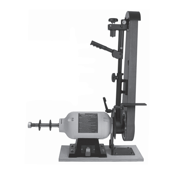
50-272
2" x 72" Belt Sander/Buffer
Operator's Manual
Record the serial number and date of purchase in your manual for future reference.
Serial Number: _________________________
Date of purchase: _________________________
For technical support or parts questions, email techsupport@rikontools.com or call toll free at (877) 884-5167
www.rikontools.com
50-272M1a
Advertisement
Table of Contents

Related Manuals for Rikon Power Tools 50-272


Summary of Contents for Rikon Power Tools 50-272
- Page 1 50-272 2” x 72” Belt Sander/Buffer Operator’s Manual Record the serial number and date of purchase in your manual for future reference. Serial Number: _________________________ Date of purchase: _________________________ For technical support or parts questions, email techsupport@rikontools.com or call toll free at (877) 884-5167 www.rikontools.com...
-
Page 2: Table Of Contents
Wiring Diagram..........................16 Warranty .............................16 Accessories ..........................17 Parts Diagram ..........................18 Parts List ..........................19 SPECIFICATIONS #50-272 Motor .......... 1HP, 110/220V, 14/7A, 60Hz, 1Ph Motor Speed ..............1,720 RPM Belt Size ............. 2” x 72” or 2” x 76” Belt Speed ..............3,600 SFPM Belt Arm Tilt ................ - Page 3 SAFETY SYMBOLS IMPORTANT! Safety is the single most important consideration in the operation of this equipment. The following instructions must be followed at all times. Failure to follow all instructions listed below may result in electric shock, fire, and/or serious personal injury. There are certain applications for which this tool was designed.
-
Page 4: Safety Instructions
SAFETY INSTRUCTIONS 12. KEEP PROTECTIVE GUARDS IN PLACE AND IN 25. ALWAYS WEAR A DUST MASK TO PREVENT WORKING ORDER. INHALING DANGEROUS DUST OR AIRBORNE PARTICLES, including wood dust, crystalline silica dust 13. AVOID ACCIDENTAL STARTING. Make sure that and asbestos dust. Direct particles away from face and the power switch is in the “OFF”... - Page 5 SAFETY INSTRUCTIONS EXTENSION CORDS ELECTRICAL SAFETY THIS TOOL MUST BE GROUNDED WHILE IN USE TO PROTECT THE OPERATOR FROM THE USE OF AN EXTENSION CORD ELECTRIC SHOCK. WITH THIS MACHINE IS NOT RECOMMENDED. For IN THE EVENT OF A MALFUNCTION OR BREAKDOWN, best power and safety, plug the machine directly into a grounding provides the path of least resistance for electric dedicated, grounded electrical outlet that is within the...
- Page 6 SAFETY INSTRUCTIONS This machine is intended for the surfacing of woods, metals and composite materials. Any other use not as specified, including modification of the machine or use of parts not tested and approved by the equipment manufacturer can cause unforeseen damage, and invalidate the warranty. ATTENTION: Use of this sander still presents risks that cannot be eliminated by the manufacturer.
-
Page 7: Contents Of Package
CONTENTS OF PACKAGE UNPACKING AND CLEAN-UP 1. Carefully remove all contents from the shipping carton. Compare the contents with the list of contents to make sure that all of the items are accounted for, before discarding any packing material. Place parts on a protected surface for easy identification and assembly. -
Page 8: Getting To Know Your Sander
GETTING TO KNOW YOUR SANDER ON/OFF Safety Switch Motor Base with Mounting Holes Buffing/Sanding 1” x 8” Spindle #50-272 Hex Nut 1” - UNC L.H. 2” x 72” Flanges Belt Sander Motor Assembly / Buffer Locking Handle to Pivot Sanding... -
Page 9: Assembly
THE MACHINE MUST NOT BE PLUGGED IN AND THE POWER SWITCH MUST BE IN THE OFF POSITION UNTIL FULL ASSEMBLY AND ALL The 50-272 Belt Sander / Buffer is ADJUSTMENTS ARE COMPLETE. a top-heavy machine and needs to be bolted down to prevent it from tipping over during use. - Page 10 ASSEMBLY & ADJUSTMENTS CONTINUED FROM PAGE 9 ATTACHING THE SANDING ARM ASSEMBLY HOLE NOTE: The Locking Lever Handles (G & H) are spring loaded. Behind the screw in the middle of the UPPER 2” X72” SANDING BELTS handle there is a spring. To position the handle in a new location, just pull out the handle, rotate it to a new direction, and push the handle back onto place.
-
Page 11: Adjustments
ADJUSTMENTS ADJUSTING THE TOOL REST THE MACHINE MUST NOT BE PLUGGED IN AND THE POWER SWITCH MUST BE The Tool Rest, or Belt Table, is fully adjustable for IN THE OFF POSITION UNTIL FULL ASSEMBLY AND setting angles to the belt from 90 degrees to over 50 ALL ADJUSTMENTS ARE COMPLETE. - Page 12 BELT SANDING ARM ADJUSTMENT LOCKING LEVER HANDLE The #50-272 Belt Sander’s sanding arm adjusts 180 degrees, from a forward horizontal position, to 90 degrees upward, to laying backwards horizontally. This allows full user access to working on the 8” rubber-...
-
Page 13: General Use
GENERAL USAGE Buffing wheels are used for hand held use for polish- ALWAYS WEAR EYE AND ing, sharpening, and cleaning operations on wood, RESPIRATORY PROTECTION! Residue from the metal, plastics or composite materials. The rotating buffing wheels and any buffing compound on the fabric can be treated with buffing compounds, paste or wheels are thrown off during use and may cause injury. -
Page 14: Troubleshooting
TROUBLESHOOTING Service on these tools should only be performed by an authorized, qualified technician. SYMPTOM PROBABLE CAUSE CORRECTIVE ACTION Motor will not start. 1. Low voltage 1. Check power source for proper voltage. 2. Open circuit in motor or loose 2. -
Page 15: Maintenance
TROUBLESHOOTING SYMPTOM PROBABLE CAUSE CORRECTIVE ACTION Burn marks on workpiece. 1. Using a sanding grit that is too 1. Use a coarser-grit sandpaper. fine. 2. Reduce work piece pressure on 2. Using too much pressure. the sandpaper while sanding. 3. Work held still for too long 3. -
Page 16: Wiring Diagram
WIRING DIAGRAM This machine must be grounded. Replacement of the power supply cable should only be done by a qualified electrician. See page 5 for additional electrical information. As received from the factory, your machine is ready to run at 110V operation. It can be switched to 220V according to the schematic below. -
Page 17: Accessories
��J� B 50-272 BELT SANDER/GRINDER MOUNTING DIAGRAM The 50-272 Belt Sander/Buffer has two parts, motor and belt assemblies. Once assembled together, they must be mounted securely to a workbench or stand before operation can begin. The diagram below shows the loca- fLf ir[IJ tion of holes that must be bored in your bench or stand for the machine. -
Page 18: Parts Diagram
PARTS DIAGRAM... -
Page 19: Parts List
PARTS LIST... - Page 20 50-272 For more information: 25 Commerce Way North Andover, MA 01845 877-884-5167 / 978-528-5380 techsupport@rikontools.com Link to RIKON’s website www.rikontools.com 50-272M1a...
Need help?
Do you have a question about the 50-272 and is the answer not in the manual?
Questions and answers