Table of Contents
Advertisement
50-122
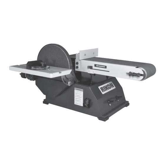
6" x 48" Belt & 10" Disc Sander
with Stand
226002
Operator's Manual
Record the serial number and date of purchase in your manual for future reference.
Serial Number: _________________________
Date of purchase: _________________________
For technical support or parts questions, email techsupport@rikontools.com or call toll free at (877)884-5167
www.rikontools.com
50-122M2
Advertisement
Table of Contents

Related Manuals for Rikon Power Tools 50-122


Summary of Contents for Rikon Power Tools 50-122
- Page 1 50-122 6” x 48” Belt & 10” Disc Sander with Stand 226002 Operator’s Manual Record the serial number and date of purchase in your manual for future reference. Serial Number: _________________________ Date of purchase: _________________________ For technical support or parts questions, email techsupport@rikontools.com or call toll free at (877)884-5167 www.rikontools.com...
-
Page 2: Table Of Contents
Changes and improvements may be made at any time, with no obligation on the part of Rikon Power Tools, Inc. to modify previously delivered units. Reasonable care has been taken to ensure that the information in this manual is correct, to provide you with the guidelines for the proper safety,... -
Page 3: Safety Instructions
SAFETY INSTRUCTIONS IMPORTANT! Safety is the single most important consideration in the operation of this equipment. The following instructions must be followed at all times. Failure to follow all instructions listed below may result in electric shock, fire, and/or serious personal injury. There are certain applications for which this tool was designed. - Page 4 SAFETY INSTRUCTIONS 12. KEEP PROTECTIVE GUARDS IN PLACE AND IN 25. ALWAYS WEAR A DUST MASK TO PREVENT WORKING ORDER. INHALING DANGEROUS DUST OR AIRBORNE PARTICLES, including wood dust, crystalline silica dust 13. AVOID ACCIDENTAL STARTING. Make sure that and asbestos dust. Direct particles away from face and the power switch is in the “OFF”...
-
Page 5: Electricals & Wiring Diagram
SAFETY INSTRUCTIONS EXTENSION CORDS ELECTRICAL SAFETY THE USE OF AN EXTENSION CORD THIS TOOL MUST BE GROUNDED WITH THIS MACHINE IS NOT RECOMMENDED. For WHILE IN USE TO PROTECT THE OPERATOR FROM best power and safety, plug the machine directly into a ELECTRIC SHOCK. - Page 6 SAFETY INSTRUCTIONS SPECIFIC SAFETY INSTRUCTIONS FOR SANDERS This machine is intended for the surfacing of natural, solid woods. Any other use not as specified, including modification of the machine or use of parts not tested and approved by the equipment manufacturer can cause unforeseen damage.
-
Page 7: Getting To Know Your Machine
R. Hex Wrench Tool Holder CONTENTS OF PACKAGE Model 50-122 Sander is shipped complete in one box. UNPACKING AND CLEAN-UP 1. Carefully remove all contents from the shipping carton. Compare the contents with the list of contents to make sure that all of the items are accounted for, before discarding any packing material. -
Page 8: Assembly
CONTENTS OF PACKAGE 50-122 6” x 48” Belt & 10” Disc Sander 226002 Operator’s Manual Record the serial number and date of purchase in your manual for future reference. Serial Number: _________________________ Date of purchase: _________________________ For technical support or parts questions, email techsupport@rikontools.com or call toll free at (877)884-5167 www.rikontools.com... - Page 9 ASSEMBLY NOTE: The 50-122 Sander includes a steel stand to mount the sander upon. There are two options for assembling the machine and also the stand: 1- The machine can be assembled first, using a workbench or table surface for this process. Then the stand can be assembled and the sander bolted onto it.
- Page 10 THE MACHINE MUST NOT BE PLUGGED IN AND THE POWER SWITCH MUST BE IN THE 'OFF' POSITION UNTIL ASSEMBLY IS COMPLETE. MOUNTING PSA SANDPAPER DISCS NOTE: The 50-122 Sander only uses 10” diameter abrasive sanding discs with Pressure Sensitive COVER Adhesive (PSA) backing.
-
Page 11: Adjustments
ASSEMBLY 9. Insert the steel rod (from step 5) through the lower hole in the right side of the frame. FIG. 8A. The rod should extend under the table to the other end of the frame, where it should exit through the large hole in the left frame. - Page 12 ADJUSTMENTS THE MACHINE MUST NOT BE PLUGGED IN AND THE POWER SWITCH MUST BE IN THE OFF POSITION UNTIL ALL ADJUSTMENTS ARE COMPLETE. 1/16” DISC TABLE ADJUSTMENTS CONTINUED To avoid jamming the work piece or fingers between the table and sanding surface, the table edge should be set to a FIG.
- Page 13 ADJUSTMENTS THE MACHINE MUST NOT BE PLUGGED IN AND THE POWER SWITCH MUST BE IN THE 'OFF' POSITION UNTIL ASSEMBLY IS COMPLETE. #50-122 DRIVE BELT ADJUSTMENTS ADJUSTING THE V-BELT TENSION Should the rotation of the sanding belt or disc slow down or stall, the cause may be that the V-belt is slipping on the two pulleys.
- Page 14 ADJUSTMENTS THE MACHINE MUST NOT BE PLUGGED IN AND THE POWER SWITCH MUST BE IN THE 'OFF' POSITION UNTIL ASSEMBLY IS COMPLETE. REPLACING THE V-BELT CONTINUED FROM PAGE 13 NOTE: Replacing the V-Belt requires that the Belt Cover, bottom Base Cover, and whole Sanding Disc Assembly be removed in order to gain access to the drive shafts and pulleys.
- Page 15 ADJUSTMENTS THE MACHINE MUST NOT BE PLUGGED IN AND THE POWER SWITCH MUST BE IN THE OFF POSITION UNTIL ALL ADJUSTMENTS ARE COMPLETE. 6. Unscrew the Disc Frame from the sander’s cabinet. Remove three screws - two on top of the frame (#38) and one longer screw from the interior of the frame (#91).
-
Page 16: Operation
OPERATION CHANGING THE SANDING BELT 1. Remove the plastic Side Cover (#60) from the frame by unscrewing the knob (#78). FIG. 25. 2. Remove the Small Fence (#56). See page 9 for instructions on installing this part. 3. Slide Tension Lever (#71) to the right to release the belt tension. - Page 17 OPERATION CHANGING THE SANDING DISC THE MACHINE MUST NOT BE PLUGGED IN AND THE POWER SWITCH MUST BE IN THE The sandpaper disc can be removed with the table OFF POSITION UNTIL ALL ADJUSTMENTS ARE COMPLETE. installed, FIG. 29, or with the table removed to give more working access to the disc, if needed.
- Page 18 OPERATION MITER GAUGE The Miter Gauge (#110) can be used on the disc table, which has a slot to fit the miter gauge’s bar. The miter gauge head can be set anywhere up to 45º (right or left) by loosening the lock-knob, setting the miter gauge head to the desired angle, and retightening the lock-knob.
-
Page 19: Maintenance
120 volt electrical receptacle. Plug The illustration on page 5 shows the type of the 120v, 3-wire electrical plug and electrical receptacle that has a grounding Earth Earth conductor that is required. 50-122 Wireing V2 Provide by Wang... -
Page 20: Troubleshooting
TROUBLESHOOTING Service on these tools should only be performed by an authorized, qualified technician. SYMPTOM PROBABLE CAUSE CORRECTIVE ACTION Motor will not start. 1. Low voltage 1. Check power source for proper voltage. 2. Open circuit in motor or loose 2. -
Page 21: Accessories
TROUBLESHOOTING SYMPTOM PROBABLE CAUSE CORRECTIVE ACTION Burn marks on work piece. 1. Using a sanding grit that is too 1. Use a coarser-grit sandpaper. fine. 2. Reduce work piece pressure on the 2. Using too much pressure. sandpaper while sanding. 3. -
Page 22: Sander Parts Diagram
PARTS DIAGRAM... -
Page 23: Sander Parts List
PARTS LIST KEY NO. RIKON PART NO. DESCRIPTION RIKON PART NO. DESCRIPTION KEY NO. Star-head screw & washer M4x6 P50-122-1 Bushing P50-122-63 Star-head screw & washer M4x8 P50-122-2 Driven drum support P50-122-64 Base cover P50-122-3 Special nut P50-122-65 Star-head screw M5x8 P50-122-4 Belt tracking knob P50-122-66... -
Page 24: Stand Parts Diagram & Parts List
PARTS DIAGRAM & PARTS LIST STAND FOR 50-122 SANDER NOTE: Please reference the Manufacturer’s Part Number when calling for Replacement Parts. For Parts under Warranty, the Serial Number of your machine is required. KEY NO. DESCRIPTION QTY. MFG. PART NO. -
Page 25: Stand Assembly
ASSEMBLY STAND ASSEMBLY 1. Connect leg (#5) with the upper long bar (#1) 2. Connect another leg (#5) to the other end of with two nuts and bolts (#6 & 7). FIG. 1. the upper long bar (#1) in step 1. FIG. 2. FIG. -
Page 26: Notes
NOTES Use this section to record maintenance, service and any calls to Technical Support:... - Page 28 50-122 For more information: 16 Progress Road Billerica, MA 01821 877-884-5167 / 978-528-5380 techsupport@rikontools.com www.rikontools.com 50-122M2...
Need help?
Do you have a question about the 50-122 and is the answer not in the manual?
Questions and answers