Table of Contents
Advertisement
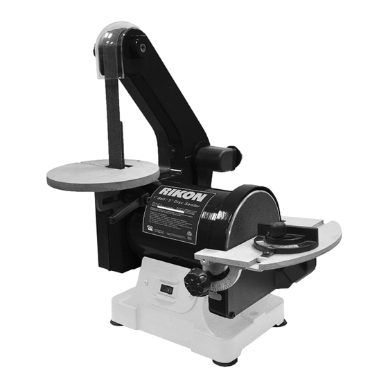
50-151
1" X 30" Belt / 5" Disc Sander
Operator's Manual
Record the serial number and date of purchase in your manual for future reference.
Serial Number: _________________________
Date of purchase: _________________________
For technical support or parts questions, email techsupport@rikontools.com or call toll free at (877)884-5167
www.rikontools.com
50-151M2
Advertisement
Table of Contents

Related Manuals for Rikon Power Tools 50-151


Summary of Contents for Rikon Power Tools 50-151
- Page 1 50-151 1” X 30” Belt / 5” Disc Sander Operator’s Manual Record the serial number and date of purchase in your manual for future reference. Serial Number: _________________________ Date of purchase: _________________________ For technical support or parts questions, email techsupport@rikontools.com or call toll free at (877)884-5167 www.rikontools.com...
-
Page 2: Table Of Contents
Changes and improvements may be made at any time, with no obligation on the part of Rikon Power Tools, Inc. to modify previously delivered units. Reasonable care has been taken to ensure that the information in this manual is correct, to provide you with the guidelines... - Page 3 SAFETY SYMBOLS The purpose of safety symbols is to attract your attention to possible dangers. The safety symbols and the explanations with them deserve your careful attention and understanding. The symbol warnings do not, by themselves, eliminate the danger. The instructions and warnings they give are no substitutes for proper accident prevention measures.
-
Page 4: General Safety
SAFETY INSTRUCTIONS IMPORTANT! Safety is the single most important consideration in the operation of this equipment. The following instructions must be followed at all times. There are certain applications for which this tool was designed. We strongly recommend that this tool not be modified and/ or used for any other application other than that for which it was designed. -
Page 5: Electrical Safety
SAFETY INSTRUCTIONS 16. NEVER LEAVE A RUNNING TOOL UNATTENDED. 26. USE A PROPER EXTENSION CORD IN GOOD Turn the power switch to the “OFF” position. DO NOT CONDITION. When using an extension cord, be sure to leave the tool until it has come to a complete stop. use one heavy enough to carry the current your product will draw. -
Page 6: Safety Instructions..............................................................................................................................3
SAFETY INSTRUCTIONS ELECTRICAL SAFETY EXTENSION CORDS (Continued) DO NOT MODIFY THE PLUG PROVIDED. Keep the extension cord clear of the If it will not fit the electrical receptacle, have the proper working area. Position the cord so that it will not get electrical receptacle installed by a qualified electrician. - Page 7 SAFETY INSTRUCTIONS SPECIFIC SAFETY INSTRUCTIONS FOR BELT & DISC SANDERS 1. Do not operate this machine until you have read all of the following instructions. 2. Do not attempt to operate this machine until it is completely assembled. 3. Do not turn ON this machine if any pieces are damaged or missing. 4.
-
Page 8: Contents Of Package
CONTENTS OF PACKAGE Carefully unpack your sander from its carton, and check to make sure the following parts are included. If any parts are missing or broken, please call RIKON Customer Service (877-884-5167) as soon as possible for replacements. DO NOT turn your machine ON if any of these items are missing. You may cause injury to yourself or damage to the machine. -
Page 9: Getting To Know Your Sander
GETTING TO KNOW YOUR SANDER Item Description Item Description Sanding Belt 1” x 30” Sanding Disc 5” (PSA) Sanding Belt Tracking Knob Disc Table Sanding Belt Table Miter Gauge Sanding Belt Table Lock Handle Motor Sanding Belt Safety Cover Sanding Belt Safety Cover ON/OFF Switch Sanding Belt Dust Port Disc Table Lock Handle... -
Page 10: Assembly
ASSEMBLY ASSEMBLY AND INSTALLATION Always ensure the sander is unplugged prior to attempting any assembly, Lag Bolt Machine Bolt installation or changing of parts and accessories. Washer MOUNTING THE SANDER TO A WORKBENCH Machine Base CAUTION: If during operation there is any tendency for the sander to tip over, slide or walk on the Rubber Foot supporting surface, the sander should be properly... - Page 11 ASSEMBLING THE SANDING DISC TABLE Always ensure the sander is discon- nected from the power supply prior to commencing work. 1. Attach the disc-sanding table (#64) to the sanding disc guard (#71) by tipping the table up, and slide the two small nipples extending from the rectangular mouth of the table, onto the 2 ‘L’...
- Page 12 INSTALLING & CHANGING SANDING DISCS Turn the power off and remove the plug from the outlet before changing the accessories. DISC TABLE ADJUSTMENTS Ensure sander is disconnected from the power supply prior to commencing work. 1. To check the trueness of the 90º angle of the disc-sanding table, place a square or other measur- FIG.
- Page 13 INSTALLING & CHANGING SANDING BELTS Turn the power off and remove the plug from the outlet before changing the accessories. Tracking Knob SANDING BELT REMOVAL: 1. Remove the lock-knob (#25), clear plastic belt guard (#26), and three Phillips screws (#21) that secure the side cover (#27) to the sander’s frame.
-
Page 14: General Use
GENERAL USAGE GENERAL USE AND OPERATING INSTRUCTIONS ON/OFF SWITCH The rocker ON/OFF power switch is located on the front of the sander. 1. Press the side marked ON to turn the sander on. 2. Press the side marked OFF to turn the sander off. BELT SANDER PLATEN The platen (# 22) is a heavy steel support plate that is positioned behind the sanding belt, rising from... -
Page 15: Troubleshooting
TROUBLESHOOTING Service on these tools should only be performed by an authorized, qualified technician. SYMPTOM PROBABLE CAUSE CORRECTIVE ACTION Motor will not start. 1. Low voltage 1. Check power source for proper 2. Open circuit in motor or loose voltage. connections. -
Page 16: Wiring Diagram
SYMPTOM PROBABLE CAUSE CORRECTIVE ACTION Burn marks on workpiece. 1. Using a sanding grit that is too 1. Use a coarser-grit sandpaper. fine. 2. Reduce work piece pressure on 2. Using too much pressure. the sandpaper while sanding. 3. Work held still for too long 3. -
Page 17: Parts Explosion
PARTS EXPLOSION... -
Page 18: Parts List
PARTS LIST KEY NO. DESCRIPTION QTY. MFG. PART NO. KEY NO. DESCRIPTION QTY. MFG. PART NO. Phillips Head Screw with Flat Washer M6 x 18mm P50-151-1 Hexagon Head Bolt M10 x 25mm P50-151-38 Rubber Foot P50-151-2 Sanding Belt Frame P50-151-39 Phillips Head Screw with Flat Washer M4 x 12mm P50-151-3 Hex Socket Screw... -
Page 19: Warranty
WARRANTY WARRANTY... - Page 20 50-151 For more information: 16 Progress Rd Billerica, MA 01821 877-884-5167 / 978-528-5380 techsupport@rikontools.com www.rikontools.com 50-151M2...
Need help?
Do you have a question about the 50-151 and is the answer not in the manual?
Questions and answers