Table of Contents
Advertisement
Quick Links
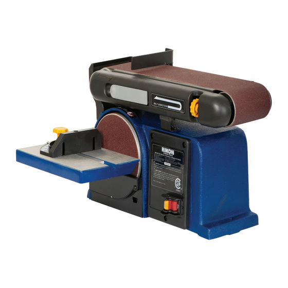
4" X 36"Belt / 6"Disc Sander
Model: 50-112
Record the serial number and date of purchase
in your manual for future reference.
Serial number:
Date of purchase:
For more information:
www.rikontools.com
info@rikontools.com
or
For Parts or Questions:
techsupport@rikontools.com or 877-884-5167
Part # 50-112M1
Advertisement
Table of Contents

Summary of Contents for Rikon Power Tools 50-112
- Page 1 4” X 36”Belt / 6”Disc Sander Model: 50-112 Record the serial number and date of purchase in your manual for future reference. Serial number: Date of purchase: For more information: www.rikontools.com info@rikontools.com For Parts or Questions: techsupport@rikontools.com or 877-884-5167 Part # 50-112M1...
- Page 2 Operator Safety: Required Reading IMPORTANT! Safety is the single most important consideration in the operation of this equipment. The following instructions must be followed at all times. There are certain applications for which this tool was designed. We strongly recommend that this tool not be modified and/or used for any other application other than that for which it was designed.
- Page 3 ALWAYS DISCONNECT TOOLS. Disconnect tools before servicing and when changing accessories such as blades, bits, and cutters. ALWAYS AVOID ACCIDENTAL STARTING. Make sure switch is in “OFF” position before plugging in cord. NEVER LEAVE TOOLS RUNNING UNATTENDED. ALWAYS CHECK FOR DAMAGED PARTS. Before initial or continual use of the tool, a guard or other part that is damaged should be checked to assure that it will operate properly and perform its intended function.
-
Page 4: Table Of Contents
37 lbs Unpacking When unpacking, check to make sure the following parts are included. If any parts are missing or broken, please call RIKON Power Tools at the number on the cover of this manual as soon as possible. Item #... -
Page 5: Assembly
Assembly Securing Sander Base Assembly to Workbench Belt and disc sander must be fastened securely to a firm supporting surface such as a workbench. OUTLINE OF 2 HOLES SANDER 10mm(3/8” Diameter) 68mm 2-21/32” 19mm (3/4”) 341mm 14mm (13-7/16”) (9/16”) Place sander in operational position on workbench. Place a pencil through the holes in the sander base (42) and mark drill holes in workbench. - Page 6 Assembly Installing Work support Place work support (60) over sanding belt as shown in following illustration. Place the hex. screw (91) through the flat washer (90)and secure. Do not over tighten. Work Support (60) Wrench Table Support Assembly Locate the table support (33) and hex. screws (31) and washers (32). Stand table (35) on its side, aligning holes as shown in below illustration.
-
Page 7: Operation
Assembly 4. Position table support (33) in corresponding holes on side of base as shown in below illustration. Index Pin Table Support (33) Base Washer (32) Knob (34) 5. Place washer (32) on knob (34) shaft and insert through slot into threaded holes in base. 6. -
Page 8: Leveling The Table Assembly
Operation Remounting Table for Vertical Sanding Remove backstop lock bolt and remove work support. Unscrew knob (34) and remove. Pull table support (33) index pin out of mounting hole. Loosen hex socket screw (75) and raise sanding bed to the desired sanding position. Insert the table index pins into the auxiliary (upper) holes in the sanding bed. - Page 9 Operation Installing and Adjusting the Sanding Belt Turn power switch to the OFF position and disconnect power cord from the main elec tricity supply. Move tension lever (66) to the right to release the sanding belt tension (10). . Place the sanding belt over the drive and idler drums (13 and 65), making sure that the inside direction arrow points down, towards the drive drum (13) as shown in illustration..
-
Page 10: Electrical Requirements
Electrical Requirements In the event of a malfunction or breakdown, grounding provides a path of least resistance for electric current to reduce the risk of electric shock. This tool is equipped with an electric cord having an equipment-grounding conductor and a grounding plug. The plug must be plugged into a matching outlet that is properly installed and grounded in accordance with all local codes and ordinances. -
Page 11: Wiring Diagram
Wiring Diagram WARNING:This machine must be grounded. Replacement of the power supply cable should only be done by a qualified electrician. Maintenance Use this section to record maintenance, service and any calls to Technical Support:... -
Page 12: Maintenance
Maintenance Apply a light coat of wax paste to the worktable to make feeding stock easier. Use a vacuum cleaner and brush to clear out dust and debris from sander and motor. Timing Drive Belt Replacement Using a Phillips screwdriver, remove the screw (66) from belt cover (67), and remove cover. -
Page 13: Troubleshooting
Maintenance Place drive belt around drive pulley (71), then drive pulley (78). Tighten the three screws slightly. Adjust tension of drive belt by placing a standard screwdriver in the adjusting hole by pushing up on the screwdriver to apply tension to the drive belt. Tighten the three screws again. - Page 14 Parts List Part No. Description Part No. Description 50-112-1 Phillips Screw M4X6 50-112-46 Idler Shaft 50-112-2 Flat Washer D4 50-112-47 Phillips Screw M5X20 50-112-3 Base Cover 50-112-49 Screw Bushing 50-112-4 Phillips Screw ST4.2X10 50-112-50 Draw Extend Spring 50-112-5 Toothed Lock Washer D4...
-
Page 15: Parts List/Parts Explosion
Parts Explosion... - Page 16 Notes...
- Page 17 Warranty 5-Year Limited Warranty RIKON Power Tools Inc. (“Seller”) warrants to only the original retail consumer/purchaser of our products that each product be free from defects in materials and workmanship for a period of five (5) years from the date the product was purchased at retail. This warranty may not be transferred.
- Page 18 For more information: 16 Progress Rd Billerica, MA 01821 877-884-5167 / 978-528-5380 techsupport@rikontools.com www.rikontools.com Copyright RIKON Power Tools, Inc. 2011 Printed in China 3/11...


Need help?
Do you have a question about the 50-112 and is the answer not in the manual?
Questions and answers