Table of Contents
Advertisement
Quick Links
50-120
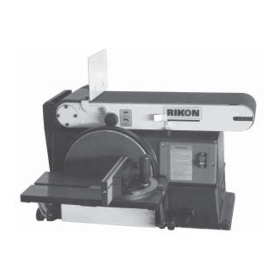
6" x 48" Belt & 10" Disc Sander
Operator's Manual
Record the serial number and date of purchase in your manual for future reference.
The serial number can be found on the specification label on the rear of your machine.
Serial Number: _________________________
Date of purchase: _________________________
For technical support or parts questions, email techsupport@rikontools.com or call toll free at (877) 884-5167
www.rikontools.com
50-120M5
Advertisement
Table of Contents

Related Manuals for Rikon Power Tools 50-120


Summary of Contents for Rikon Power Tools 50-120
- Page 1 50-120 6” x 48” Belt & 10” Disc Sander Operator’s Manual Record the serial number and date of purchase in your manual for future reference. The serial number can be found on the specification label on the rear of your machine.
-
Page 2: Table Of Contents
NOTE: The specifications, photographs, drawings and information in this manual represent the current model when the manual was prepared. Changes and improvements may be made at any time, with no obligation on the part of Rikon Power Tools, Inc. to modify previously delivered units. Reasonable care has been taken to ensure that the information in this manual is correct, to provide you with the guidelines for the proper safety, assembly and operation of this machine. - Page 3 SAFETY SYMBOLS IMPORTANT! Safety is the single most important consideration in the operation of this equipment. The following instructions must be followed at all times. Failure to follow all instructions listed below may result in electric shock, fire, and/or serious personal injury. There are certain applications for which this tool was designed.
- Page 4 SAFETY INSTRUCTIONS 12. KEEP PROTECTIVE GUARDS IN PLACE AND IN 25. ALWAYS WEAR A DUST MASK TO PREVENT WORKING ORDER. INHALING DANGEROUS DUST OR AIRBORNE PARTICLES, including wood dust, crystalline silica dust 13. AVOID ACCIDENTAL STARTING. Make sure that and asbestos dust. Direct particles away from face and the power switch is in the “OFF”...
-
Page 5: Electrical Requirements
SAFETY INSTRUCTIONS ELECTRICAL SAFETY EXTENSION CORDS THIS TOOL MUST BE GROUNDED WHILE IN USE TO PROTECT THE OPERATOR FROM THE USE OF AN EXTENSION CORD ELECTRIC SHOCK. WITH THIS MACHINE IS NOT RECOMMENDED. For IN THE EVENT OF A MALFUNCTION OR BREAKDOWN, best power and safety, plug the machine directly into a grounding provides the path of least resistance for electric dedicated, grounded electrical outlet that is within the... -
Page 6: Sander Safety Rules
SAFETY INSTRUCTIONS This machine is intended for the surfacing of woods, metals and composite materials. Any other use not as specified, including modification of the machine or use of parts not tested and approved by the equipment manufacturer can cause unforeseen damage, and invalidate the warranty. ATTENTION: Use of this sander still presents risks that cannot be eliminated by the manufacturer. -
Page 7: Contents Of Package
CONTENTS OF PACKAGE When unpacking, check to make sure the following parts are included. If any parts are missing or broken, please call RIKON Power Tools at the number on the cover of this manual as soon as possible. Carton Contents Item Description Belt &... -
Page 8: Assembly
ASSEMBLY Securing Sander Base Assembly to Workbench THE MACHINE MUST NOT BE PLUGGED IN AND THE The sander base must be secured before using. POWER SWITCH MUST BE IN THE 'OFF' Attach a large C-Clamp to each side of the sander POSITION UNTIL ASSEMBLY IS COMPLETE. - Page 9 ASSEMBLY Installing the Disc Table Assembly To avoid jamming the workpiece or fingers between the table and sanding surface, the table edge should be a maximum of 1/16 inch from the sanding surface. 1. Use two M6x16 pan head screws to fasten the table support mount to the front of the sander.
- Page 10 ASSEMBLY Installing the Sanding Belt To avoid injury from accidental start, make sure the machine is unplugged before making any adjustments. On the under side of the sanding belt, you will find a “direction arrow”. The sanding belt must run in the direction of this arrow, so that the splice does not come apart.
-
Page 11: Operation
OPERATION Bevel Sanding The work table can be tilted from 0 to 45 degrees for bevel sanding. Loosen the table lock knob and tilt the work table to desired angle as shown. (See Fig. 12) Re-tighten the table lock knob. To avoid jamming the workpiece or fingers between the table and sanding surface, the table should repositioned on the table support to... - Page 12 OPERATION End Sanding on the Sanding Belt To sand the end of a long workpiece, it is recommend- ed to sand with the belt in the vertical position. 1. To raise the belt to the vertical position, follow the instructions in “Positioning Belt Bed” on the previous page.
-
Page 13: Maintenance
MAINTENANCE For your safety, remove the plug from power source outlet before adjusting, maintaining, of lubricating your belt and disc sander. 1. Apply a light coat of paste wax to the work table to make feeding stock easier, and reduce rust. 2. -
Page 14: Parts Diagram
Parts Diagram PARTS DIAGRAM... -
Page 15: Parts List
PARTS LIST... - Page 16 Parts Diagram PARTS DIAGRAM...
- Page 17 PARTS LIST...
-
Page 18: Troubleshooting
Troubleshooting TROUBLESHOOTING SYMPTOM PROBABLE CAUSE REMEDY Sander does not operate 1. Not plugged into wall outlet. 1. Plug into wall outlet. 2. Locking key is not inserted. 2. Insert locking key. 3. Power switch defective. 3. Replace power switch. 4. Motor or wiring problem. 4. -
Page 19: Accessories
ACCESSORIES SANDING BELTS SANDING DISCS 6” x 48” Aluminum Oxide 10” Diameter, PSA Aluminum Oxide 50-6080 80 Grit Pack of 2 50-10060 60 Grit Pack of 2 50-6120 120 Grit Pack of 2 50-10080 80 Grit Pack of 2 50-6150 150 Grit Pack of 2 50-10120... - Page 20 50-120 For more information: 25 Commerce Way North Andover, MA 01845 877-884-5167 / 978-528-5380 techsupport@rikontools.com www.rikontools.com 50-120M5...
Need help?
Do you have a question about the 50-120 and is the answer not in the manual?
Questions and answers
The belt keeps moving towards the back of the sander.
To fix the issue of the belt moving towards the back of the Rikon Power Tools 50-120 sander, adjust the belt tracking. This will align the sanding belt properly on the drums.
This answer is automatically generated