Table of Contents
Advertisement
Quick Links
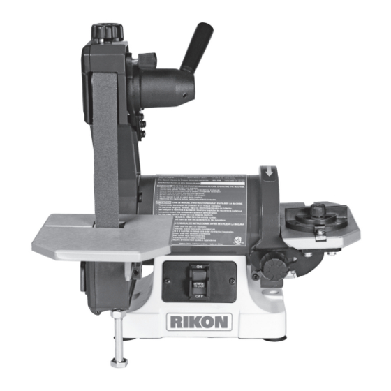
50-1305
1" X 30" Belt / 5" Disc Sander
Operator's Manual
Record the serial number and date of purchase in your manual for future reference.
Serial Number: _________________________
Date of purchase: _________________________
For technical support or parts questions, email techsupport@rikontools.com or call toll free at (877 )884-5167
www.rikontools.com
50-1305M1
Advertisement
Table of Contents

Related Manuals for Rikon Power Tools 50-1305


Summary of Contents for Rikon Power Tools 50-1305
- Page 1 50-1305 1” X 30” Belt / 5” Disc Sander Operator’s Manual Record the serial number and date of purchase in your manual for future reference. Serial Number: _________________________ Date of purchase: _________________________ For technical support or parts questions, email techsupport@rikontools.com or call toll free at (877 )884-5167 www.rikontools.com...
-
Page 2: Table Of Contents
NOTE: The specifications, photographs, drawings and information in this manual represent the current model when the manual was prepared. Changes and improvements may be made at any time, with no obligation on the part of Rikon Power Tools, Inc. to modify previously delivered units. Reasonable care has been taken to ensure that the information in this manual is correct, to... - Page 3 SAFETY SYMBOLS IMPORTANT! Safety is the single most important consideration in the operation of this equipment. The following instructions must be followed at all times. Failure to follow all instructions listed below may result in electric shock, fire, and/or serious personal injury. There are certain applications for which this tool was designed.
-
Page 4: Safety Instructions
SAFETY INSTRUCTIONS 12. KEEP PROTECTIVE GUARDS IN PLACE AND IN 25. ALWAYS WEAR A DUST MASK TO PREVENT WORKING ORDER. INHALING DANGEROUS DUST OR AIRBORNE PARTICLES, including wood dust, crystalline silica dust 13. AVOID ACCIDENTAL STARTING. Make sure that and asbestos dust. Direct particles away from face and the power switch is in the “OFF”... -
Page 5: Electrical Requirements
SAFETY INSTRUCTIONS EXTENSION CORDS ELECTRICAL SAFETY THE USE OF AN EXTENSION CORD THIS TOOL MUST BE GROUNDED WITH THIS MACHINE IS NOT RECOMMENDED. For WHILE IN USE TO PROTECT THE OPERATOR FROM best power and safety, plug the machine directly into a ELECTRIC SHOCK. -
Page 6: Sander Safety Rules
SAFETY INSTRUCTIONS SPECIFIC SAFETY INSTRUCTIONS FOR SANDERS This machine is intended for the surfacing of natural, solid woods and composite materials. Any other use not as specified, including modification of the machine or use of parts not tested and approved by the equipment manufacturer can cause unforeseen damage, and invalidate the warranty. -
Page 7: Contents Of Package
5. Set packing material and shipping carton aside. Do not discard until the machine has been set up and is running properly. 50-1305 1” X 30” Belt / 5” Disc Sander TABLE OF LOOSE PARTS A. Belt & Disc Sander Assembly E. -
Page 8: Getting To Know Your Sander
GETTING TO KNOW YOUR SANDER 50-1305 1” X 30” Belt / 5” Disc Sander Item Description Item Description Sanding Belt 1” x 30” & Platen Disc Table Lock Handle & Angle Scale Sanding Belt Cover Knob ON/OFF Switch Sanding Belt Tracking Knob Belt Table Support Bolt &... -
Page 9: Assembly
ASSEMBLY NOTE: The parts listed in the instructions refer to the THE MACHINE MUST NOT BE PLUGGED IN AND THE POWER SWITCH MUST BE IN THE OFF POSITION Parts Diagrams & Parts Lists on pages 16 to 18. UNTIL FULL ASSEMBLY AND ALL ADJUSTMENTS ARE COMPLETE. MOUNTING THE SANDER TO A WORKBENCH CAUTION: If during operation there is any tendency Lag Bolt... -
Page 10: Adjustments & General Use
ASSEMBLY & ADJUSTMENTS INSTALLING THE SANDING DISC TABLE FIG. D 1. Tilt the Disc-Sanding Table (#48) upward to slide it onto the sander”s Disc Guard Frame (#1), aligning the table Support’s semi-circular slot with the threaded hole in the frame’s side. FIG. D. 2. - Page 11 ADJUSTMENTS INSTALLING & CHANGING SANDING DISCS Turn the power off and remove the plug from the outlet before changing the accessories. SANDING DISC TABLE ADJUSTMENTS 1. To check the trueness of the 90º angle of the disc-sanding table, place a square or other measur- ing device on the table with the other end against the sanding disc.
- Page 12 ADJUSTMENTS INSTALLING & CHANGING SANDING BELTS BELT COVER REMOVED FOR PHOTO SANDING BELT REMOVAL: BELT BELT 1. Open the side Belt Cover (#70) by turning the top COVER SANDER LOCKING Locking Knob (#71)) and tilting down the hinged cover TENSION KNOB to reveal the frame’s interior parts.
-
Page 13: Maintenance
GENERAL USAGE ON/OFF SWITCH The rocker ON/OFF power switch is located on the front of the sander. FIG. M. 1. Move the switch up to turn the sander ON. 2. Move the switch down to turn the sander OFF. 3. Unplug the sander from the power source when not in use. NOTE: To prevent unauthorized use of the sander, the power switch has a removable locking key. -
Page 14: Troubleshooting
TROUBLESHOOTING SYMPTOM PROBABLE CAUSE CORRECTIVE ACTION Motor will not start. 1. Low voltage 1. Check power source for proper 2. Open circuit in motor or loose voltage. connections. 2. Inspect all lead connections on 3. Blown fuse or breaker. motor for loose or open connec- tions. -
Page 15: Wiring Diagram
Service on these tools should only be performed by an authorized, qualified technician. WIRING DIAGRAM 50-1305 BLACK 1” X 30” Belt / 5” Disc Sander WHITE This machine must be grounded. -
Page 16: Parts Explosion
PARTS EXPLOSION 50-1305 1” X 30” BELT / 5” DISC SANDER... -
Page 17: Parts List
PARTS LIST DESCRIPTION QTY. PART NO. Sanding disc guard frame P50-1305-1 Stator P50-1305-2 Rotor P50-1305-3 Bearing 6202-2RZ P50-1305-4 Wave spring washer D35 P50-1305-5 End cap P50-1305-6 Phillips screw assembly M4x153 P50-1305-7 Hex nut M4 P50-1305-8 Cord bushing P50-1305-9 Base P50-1305-10 Phillips screw assembly M6x18 P50-1305-11 Phillips screw assembly M4x7... -
Page 18: Accessories
PARTS LIST DESCRIPTION QTY. PART NO. Disc plate P50-1305-46 Phillips screw assembly M4x8 P50-1305-47 Disc work table P50-1305-48 Disc table support P50-1305-49 Disk table locking knob P50-1305-50 Big flat washer D6 P50-1305-51 Pointer P50-1305-52 Miter gauge slide bar P50-1305-53 Miter gauge P50-1305-54 Pointer P50-1305-55... -
Page 19: Warranty
WARRANTY WARRANTY... - Page 20 50-1305 For more information: 25 Commerce Way North Andover, MA 01845 877-884-5167 / 978-528-5380 techsupport@rikontools.com www.rikontools.com 50-1305M1...
Need help?
Do you have a question about the 50-1305 and is the answer not in the manual?
Questions and answers