Advertisement
Quick Links
Technical Support and E-Warranty Certificate www.vevor.com/support
Instruction Manual
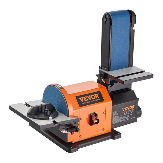
BELT & DISC SANDER
We continue to be committed to provide you tools with competitive price.
"Save Half ", "Half Price" or any other similar expressions used by us only represents an
estimate of savings you might benef it from buying certain tools with us compared to the major
top brands and doses not necessarily mean to cover all categories of tools offered by us. You
are kindly reminded to verif y caref ully when you are placing an order with us if you are
actually saving half in comparison with the top major brands.
Advertisement

Related Manuals for VEVOR BD4803


Summary of Contents for VEVOR BD4803
- Page 1 Technical Support and E-Warranty Certificate www.vevor.com/support Instruction Manual BELT & DISC SANDER We continue to be committed to provide you tools with competitive price. "Save Half ", "Half Price" or any other similar expressions used by us only represents an estimate of savings you might benef it from buying certain tools with us compared to the major top brands and doses not necessarily mean to cover all categories of tools offered by us.
- Page 2 CustomerService@vevor.com This is the original instruction, please read all manual instructions carefully before operating. VEVOR reserves a clear interpretation of our user manual. The appearance of the product shall be subject to the product you received. Please forgive us that we won't inform you again if...
- Page 3 TABLE OF CONTENTS SECTION PAGE PRODUCT SPECIFICATIONS ....................PROPOSITION 65 WARNING ................... SAFETY GUIDELINES - DEFINITIONS ................POWER TOOL SAFETY ......................BELT / DISC SANDER SAFETY .................... ELECTRICAL REQUIREMENTS AND SAFETY ..............TOOLS NEEDED FOR ASSEMBLY ..................CARTON CONTENTS ......................KNOW YOUR BELT / DISC SANDER..................
- Page 4 SAVE THESE INSTRUCTIONS SAFETY GUIDELINES - DEFINITIONS WARNING ICONS Your power tool and its Instruction Manual may contain “WARNING ICONS” (a picture symbol intended to alert you to, and/or instruct you how to avoid, a potentially hazardous condition). Understanding and heeding these symbols will help you operate your tool better and safer. Shown below are some of the symbols you may see.
- Page 5 POWER TOOL SAFETY GENERAL SAFETY INSTRUCTIONS WEAR A FACE MASK OR DUST MASK. Sanding operation produces BEFORE USING THIS POWER TOOL Safety is a combination of common sense, staying dust. alert and knowing how to use your power tool. SECURE WORK. Use clamps or a vise WARNING to hold work when practical.
- Page 6 BELT / DISC SANDER SAFETY 1. USE sander on horizontal surfaces only. 15. DO NOT sand with the workpiece unsupported. Support the workpiece Operating the sander when mounted on non-horizontal surfaces might result in with the backstop or table. Plan your motor damage.
- Page 7 ELECTRICAL REQUIREMENTS AND SAFETY POWER SUPPLY AND MOTOR SPECIFICATIONS ampere rating. If in doubt, use the next heavier gauge. The smaller the gauge number, the WARNING heavier the cord. Make sure your extension cord is properly or damage to the tool, use proper circuit wired and in good condition.
- Page 8 TOOLS NEEDED FOR CARTON CONTENTS ASSEMBLY UNPACKING AND CHECKING CONTENTS Carefully unpack the belt / disc sander and all Supplied Not Supplied its parts, and compare against the list below and the illustration on the next page. Place the belt / disc sander on a secure surface and examine it carefully.
- Page 9 UNPACKING YOUR BELT / DISC SANDER...
- Page 10 KNOW YOUR BELT / DISC SANDER Worktable scale 8 in. diameter sanding disc Belt worktable Worktable knob Disc worktable Switch Mounting hole Miter gauge Worktable handle Worktable scale Angle pointer 4 in. width / 36 in. length Belt tension lever sanding belt Belt frame connection Tracking knob...
- Page 11 ASSEMBLY AND ADJUSTMENTS INSTALLATION DISC 5. Screw the sanding disc cover in place and then install the other parts. 1. Loose all six screws fixing the sanding disc cover and remove the cover. loose the M6 x 16 left-hand Phillips screw on the motor shaft head and remove the sanding disc pad,loose the tie which binds the key.
- Page 12 Estimated Assembly Time: 10 - 20 minutes. MOUNTING WORKTABLE ON BELT (FIG. C, D ) WARNING The small worktable is used with the sanding To avoid injury, always keep the plug belt. It should be used to support workpieces disconnected from the power source and in all sanding operations except inside curve the switch turned OFF until the sander is completely assembled and adjusted properly.
- Page 13 Fig. H CAUTION Recommended Hardware between the worktable and sanding belt, (not supplied) 1. Mounting bolts the worktable edge should be positioned 2. Lock washer a maximum of 1/16 in. (1.6 mm) from 3. Hex nut 4. Sander base sanding belt. MITER GAUGE (FIG.
- Page 14 CAUTION CAUTION between the worktable and sanding disc, between the worktable and sanding belt, the worktable edge should be positioned the worktable edge should be positioned a maximum of 1/16 in. (1.6 mm) from a maximum of 1/16 in. (1.6 mm) from sanding disc plate.
- Page 15 OPERATION BELT HORIZONTAL SANDING (FIG. M) CAUTION CAUTION The belt/disc sander is designed to perform sanding operations on surface, and edge grain. between the worktable and sanding belt, The sander will also perform freehand forming the worktable edge should be positioned a and contouring operations.
- Page 16 BELT VERTICAL SANDING (FIG. O, P) Freehand sanding of outside curves should be Your belt / disc sander - belt station can sand vertically as well as horizontally. Depending on minimum of 1 in. (25.4 mm) from the sanding disc. operator needs and the workpiece, the worktable Fig.
- Page 17 MAINTENANCE REMOVE SANDING BELT ( FIG. U ,V) WARNING WARNING For your safety, turn switch OFF and To avoid injury, turn switch OFF and remove the power cord from the electrical disconnect the plug from the power source outlet before adjusting or performing before removing and installing sanding belt.
- Page 18 TROUBLESHOOTING GUIDE WARNING To avoid injury from an accidental start, turn the switch OFF and always remove the plug from the power source before making any adjustments. PLEASE READ THE FOLLOWING: The manufacturer and/or distributor is providing the buyer with a parts list and assembly diagram in this manual as a reference tool only.
- Page 19 EXPLODED VIEW...
- Page 20 TROUBLESHOOTING GUIDE SPECIFICATION SPECIFICATION Knob M6×16 Plug Big washer Poniter Miter gauge Cord clip Philips Screw +spring M5×8 Philips screw M5×8 washer+flat Washer Pointer Disc cover end cap Miter bar Tube connector Disc table Philips screw M4×10 Flat washer Lock knob assembly Disc plate Hex screw+spring M6×12...
- Page 21 Technical Support and E-Warranty Certificate www.vevor.com/support MADE IN CHINA...
Need help?
Do you have a question about the BD4803 and is the answer not in the manual?
Questions and answers