
Subscribe to Our Youtube Channel
Related Manuals for RCF C-Tec UP 9502


Summary of Contents for RCF C-Tec UP 9502
- Page 1 www.acornfiresecurity.com USER MANUAL UP 9501 - DXT 9000 SYSTEM AMPLIFIERS UP 9502 UP 9504 www.acornfiresecurity.com...
- Page 2 www.acornfiresecurity.com www.acornfiresecurity.com...
-
Page 3: Table Of Contents
www.acornfiresecurity.com TABLE OF CONTENTS SAFETY PRECAUTIONS NOTES ABOUT AUDIO SIGNAL CABLES DXT 9000 SYSTEM DESCRIPTION UP 9500 SERIES AMPLIFIER MAIN FEATURES INSTALLATION INTO A 19” RACK CABINET FRONT PANEL REAR PANEL LOUDSPEAKER CONNECTION OPERATING AS DXT 9000 SYSTEM COMPONENTS USE AS GENERIC AMPLIFIER AUDIO SET MENU CALIBRAT MENU ROUTING MENU... -
Page 4: Safety Precautions
RCF S.p.A. will not assume any responsibility for the incorrect installation and / or use of this product. WARNING: To prevent the risk of fire or electric shock, never expose this product to rain or humidity. -
Page 5: Notes About Audio Signal Cables
(screw anchors, screws, brackets not supplied by RCF etc.), which must guarantee the security of the system / installation over time, also considering, for example, the mechanical vibrations normally generated by transducers. -
Page 6: Dxt 9000 System Description
Since data wiring may have critical connections, for instance due to cable type and length, RCF FLEXCOM bus can adapt the data communication speed to the wiring characteristics and available data band. Only a few devices are necessary to design the simplest and the most complex projects, centralized or distributed: no matter if a supermarket or a theatre, an airport or a shopping centre, a fast-food or an underground, a school or a hospital. - Page 7 Each component has its own digital address. DXT 9000 includes high quality digital components already in use for RCF professional audio systems, obtaining high performances and qualifying the DXT 9000 system for installations in places that require a very good sound reproduction, such as theatres and auditoriums.
- Page 8 www.acornfiresecurity.com EXAMPLE: SYSTEM WITH MX 9504 MAIN UNIT FALLBACK EMERGENCY MIC. FIRE ALARM SYSTEM PAGING MIC. BM 9802 BM 9804 100 V / 70 V LOUDSPEAKERS LINES + BE 9808 MX 9504 MUSIC SOURCES EXAMPLE: SYSTEM WITH MU 9186 MAIN UNIT FALLBACK EMERGENCY MIC.
- Page 9 www.acornfiresecurity.com EXAMPLE: SYSTEM WITH NETWORK FALLBACK EMERGENCY MIC. PAGING MIC. BM 9802 BM 9804 FIRE ALARM + BE 9808 SYSTEM UP 9501 100 V / 70 V LOUDSPEAKER LINES MU 9186/R UP 9502 MUSIC SOURCES FALLBACK EMERGENCY FIRE ALARM MIC. SYSTEM 100 V / 70 V LOUDSPEAKERS LINES PAGING MIC.
-
Page 10: Up 9500 Series Amplifier Main Features
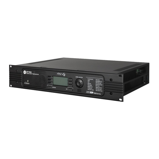
UP 9500 SERIES AMPLIFIER MAIN FEATURES UP 9500 series amplifiers are based on RCF ‘Class D+’ technology and have a FALL BACK emergency audio input, making the DXT 9000 system highly safe and reliable. These can operate as either DXT 9000 system components (linked to MU 9186 / MX 9502 / MX 9504 main units) or generic amplifiers (with limited functionality) for other audio systems. -
Page 11: Installation Into A 19" Rack Cabinet
www.acornfiresecurity.com BLOCK DIAGRAM INSTALLATION INTO A 19” RACK CABINET Fix every amplifier to the front side of a 19” rack cabinet through 4 screws. UP 9500 series amplifiers have forced ventilation controlled by a thermostat and can be stacked without spaces or ventilation panels. Air ventilation is horizontal, so it is necessary to keep open the lateral sides. -
Page 12: Front Panel
www.acornfiresecurity.com FRONT PANEL 9 10 SYSTEM ON button: press and hold to turn amplifier on (when off). This button also works as fault acknowledge: press it to remove the displayed fault indication. SYSTEM ON 48 V buTTon does noT Turn The uniT off o swiTch The uniT off make sure The dc power supply... - Page 13 www.acornfiresecurity.com ÷ LEDs T works as SILK SCREEN COLOUR Generic INDICATION (WHEN LIT) FURTHER INFORMATION amplifier The mains power (AC) is present If the LED is off, the mains power is AC PWR Green and the respective fuse is intact. not available (or out of range).
- Page 14 www.acornfiresecurity.com t works as SILK SCREEN COLOUR GENErIC INDICATION (WHEN LIT) FURTHER INFORMATION amplIfIEr The alert message is currently played. This LED also indicates the play of a message from a ALERT Yellow microphone or an external source activated as ALERT (GPI set to ALERT).
- Page 15 www.acornfiresecurity.com t works as SILK SCREEN COLOUR GENErIC INDICATION (WHEN LIT) FURTHER INFORMATION amplIfIEr This indication depends on either a broken / short-circuited cable or no COMM. PORT Hardware / RS 485 serial port (for Yellow data transmission (for example, due FAULT linking to a fire alarm system) fault.
-
Page 16: Rear Panel
www.acornfiresecurity.com REAR PANEL UP 9501 31 30 UP 9502 31 30 UP 9504 MAX OUTPUT POWER 500 W RMS Series EN54-16 MINIMUM LOAD IMPEDANCE 70 V (20 Ω) - 100 V (40 Ω) COMPLIANCE STICKER 4x125W CLASS D POWER AMPLIFIER LINE A LINE B LINE C... - Page 17 www.acornfiresecurity.com For monitoring purposes, the two CMD contacts should normally be powered by 24 V dc (voltage available from the 24 V DC . FALL BACK input state depends on presence and polarity of the voltage at the two CMD contacts. STATE VOLTAGE AT THE CMD CONTACTS DESCRIPTION...
- Page 18 www.acornfiresecurity.com LOGIC INPUT 1 ÷ 8 STATES: STATE DETECTED RESISTANCE VALUE (R) OPEN Open line or too high resistance R > 15 kΩ SHORT Short-circuit or too low resistance R < 390 Ω IDLE Used logic input, but inactive 3.4 kΩ < R < 15 kΩ ACTIVE Activated logic input 390 Ω...
- Page 19 www.acornfiresecurity.com MAX OUTPUT POWER 500 W RMS Series MINIMUM LOAD IMPEDANCE 70 V (20 ) - 100 V (40 ) LINE A1 LINE A2 LINE B1 LINE B2 INPUT OUTPUT SPARE AMP BUS – INPUT Input to link the spare amplifier 100 V / 70 V output. SPARE AMP BUS –...
-
Page 20: Loudspeaker Connection
Every loudspeaker shall have a matching transformer, which input is suitable for the line voltage (70 / 100 V). The output voltage setting (either 100 V or 70 V) can only be made by an authorised RCF service centre. UP 9501 Connect the positive wire of the loudspeaker line to the ‘+’... -
Page 21: Operating As Dxt 9000 System Components
www.acornfiresecurity.com LINE A1 LINE A2 – + – + 100 v 100 v 100 v OPERATING AS DXT 9000 SYSTEM COMPONENTS If used as DXT 9000 system components, UP 9501, UP 9502 and UP 9504 amplifiers are controlled by the main unit (MU 9186, MX 9502, MX 9504) to which they are linked and their displays indicate REMOTE CONTROLLED. -
Page 22: Audio Set Menu
www.acornfiresecurity.com Functions managed by each menu are briefly described in the following table: MENU DESCRIPTION AUDIO SET Input / output / monitor settings. CALIBRAT Amplifier calibration. ------ ROUTING Audio matrix. SYSTEM LED test, system reset and shutting down. Information about the device, its internal amplifiers and its INFO firmware. - Page 23 www.acornfiresecurity.com PARAMETERS FREQ Centre frequency setting. BAND n (I, II, III) GAIN Gain setting. BYPASS EQ Select either ON (equalizer bypassed) or OFF (equalizer inserted). LO CUT (hi-pass filter) Filter that cuts low frequencies below the cutoff frequency. It has a single parameter: the cutoff frequency. 5-BAND EQ The five bands are semi-parametric equalizers that allow to choose the centre frequency and adjust its level.
- Page 24 www.acornfiresecurity.com LEVEL Audio input level setting. AUDIO SET > OUTPUT AUDIO SET > OUTPUT SUBMENU SUBMENU Audio output parameter settings. Select an audio output among OUT 1, 2, 3, 4, to access its parameter list. Select MUTE ALL to mute or UNMUTE ALL to unmute all audio outputs. 5-BAND EQ The five bands are semi-parametric equalizers that allow to choose the centre frequency and adjust its level.
-
Page 25: Calibrat Menu
www.acornfiresecurity.com CALIBRAT MENU Calibration of each audio output (necessary for detecting line faults). Select one of the audio output OUT 1/2/3/4 (that correspond to its respective internal amplifier) to carry out its calibration. ROUTING MENU Menu concerning the audio matrix, where to match sources and destinations. After selecting an audio output (OUT 1, OUT 2, OUT 3, OUT 4), use the CONTROL SELECTION encoder to choose an audio channel (to be sent to the selected output) -
Page 26: Display Text Messages
www.acornfiresecurity.com DISPLAY TEXT MESSAGES DISPLAY TEXT MESSAGES DESCRIPTION REMOTE CONTROLLED Device controlled by a DXT 9000 system main unit. AC NOT AVAILABLE Mains AC power supply not available. AC HIGH Mains AC power supply: too high voltage. AC LOW Mains AC power supply: too low voltage. AC FUSE FLT Mains AC power supply: blown or not present fuse. -
Page 27: Internal Jumper Settings
www.acornfiresecurity.com INTERNAL JUMPER SETTINGS ImportaNt: inTernal jumper seTTinG shall be carried ouT only by eiTher or an auThorised serVice cenTre Remove the lid and look at the back GPI / GPO board (in this drawing, the 10 jumpers are marked in grey inside the rectangle): ZOOM: BC position: the two resistors for monitoring are not AB position: the two resistors for monitoring are... -
Page 28: Connection Example
www.acornfiresecurity.com CONNECTION EXAMPLE MU 9186 MU 9186/R MX 950x UP 950x BUS IN – BUS OUT www.acornfiresecurity.com... -
Page 29: Spare Amplifier (Up 9501) Connection Example
www.acornfiresecurity.com SPARE AMPLIFIER (UP 9501) CONNECTION EXAMPLE UP 9501 / 9502 / 9504 UP 9501 / 9502 / 9504 SPARE UP 9501 www.acornfiresecurity.com... -
Page 30: Guidance On The Measurement Of The Speaker Line Impedance
www.acornfiresecurity.com GUIDANCE ON THE MEASUREMENT OF THE SPEAKER LINE IMPEDANCE In the DXT 9000 system, monitoring of the integrity of speaker lines is made through impedance measurement at subsonic frequency (20 Hz). This method was chosen because of its good stability and accuracy of calculated values, which avoids false line fault reports that often occur with impedance measurements faster at supersonic frequencies, but more prone to interferences and errors. - Page 31 www.acornfiresecurity.com Amplifiers are protected and designed to operate at their maximum rated power. The best impedance range (Zmon), in which its measurement is more stable, immune to errors and repeatable, is from 50% to 100% of the load corresponding to the maximum power of the channel. With 100 V lines: 1 x 500 W →...
- Page 32 www.acornfiresecurity.com The following formula is basically the calculation of the impedances in parallel: Zmaxend Ztot Znoend = Zmaxend – Ztot NotE: 20 h The line impedance here is considered aT The frequency of which is noT equal To The one measured by an impedance meTer aT The percentage difference between the two impedances is 7.14%, so it is necessary to set the tolerance to the 5% option.
- Page 33 www.acornfiresecurity.com The total impedance (Ztot) resulting from the parallel between the load impedance already present in the line (Zline) and EOL (Zeol = 200 Ω) is easily obtainable by the following formula: Zline Zeol Ztot = Zline – Zeol NotE: (Zline) 20 h The line impedance...
-
Page 34: Specifications
- Input impedance (1 kHz): 25 kΩ Loudspeaker line outputs - Output voltage: 100 V / 70 V (selectable by RCF only) - Number of internal amplifiers: 1 (UP 9501), 2 (UP 9502), 4 (UP 9504) - Max. power of each amplifier:... -
Page 35: Appendix
DATA LINK - 1 RS485 EUROBLOCK connector - 2 RCF FLEXCOM BUS EUROBLOCK connectors ELECTRICAL SPECS. - Operating voltage: 115/230 V ac (50-60 Hz), 48 V dc - Max. consumption (power): 800 W - Operating temperature: –5 ÷ +50 °C (23 ÷ 122 °F) - Relative humidity: 20 ÷...
Need help?
Do you have a question about the C-Tec UP 9502 and is the answer not in the manual?
Questions and answers