Advertisement
Quick Links
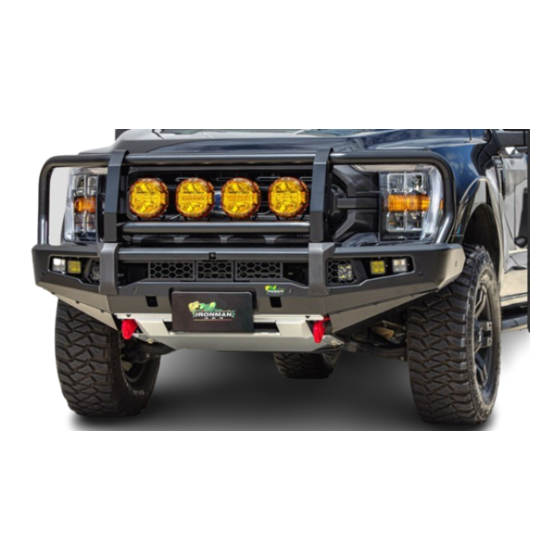
BBP109C Bar Weight: 120Kg (265Lb) | BBP109C-SL Bar Weight: 100Kg (221Lb)
OE removal weight 40Kg (88Lb)
NOTE
This bull bar should not impede the operation of the Intercooler Active Aero.
Some images contained in these instructions are generic and are a representation
of the actual model and/or parts used. Some steps may also show parts out of
sequence to the instructional steps.
SAFETY WARNING
Ironman 4X4 requires you read and understand the safety and pre-install
directions on page 2 and 3 before commencing installation of this product.
This product has been tested for airbag compatibility
and therefore the mounting system MUST NOT be modified
©Copyright 2023 Ironman 4x4 Pty Ltd. No part of this publication may be reproduced or replicated without the prior written consent of Ironman 4x4 Pty Ltd
INSTALLATION
INSTRUCTIONS
BBP109C / BBP109C-SL
BULL BARS TO SUIT FORD F-150
14th Gen (P702) 2021+
No Bumper
Cut Required
Approximately
Document Number: BBP109/081223
Document Number: BBR074/070323
5 Hours
Advertisement

Related Manuals for Ironman4x4 BBP109C


Summary of Contents for Ironman4x4 BBP109C
- Page 1 INSTALLATION INSTRUCTIONS BBP109C / BBP109C-SL BULL BARS TO SUIT FORD F-150 14th Gen (P702) 2021+ BBP109C Bar Weight: 120Kg (265Lb) | BBP109C-SL Bar Weight: 100Kg (221Lb) OE removal weight 40Kg (88Lb) NOTE No Bumper 5 Hours This bull bar should not impede the operation of the Intercooler Active Aero.
- Page 2 BBP109C / BBP109C-SL Installation Guide Pre-Installation Procedures SAFETY WARNING • It is always good practice to disconnect the battery while working on 12 Volt systems. - Please check the owner’s manual for vehicle-specific requirements as some models may need battery backup.
- Page 3 Installation Guide Installation Guide BBP109C / BBP109C-SL Warning • Ironman 4x4 recovery points are FEA tested during design and destruction tested during development to establish the Working Load Limits (WLL). • Ironman 4x4 recovery points have been designed as a matching pair, supplied as right and left sides for vehicle-specific fitment.
- Page 4 Recovery point warning sticker (not shown) 24a. Chassis mount inner bracket - RHS Sensor holders (PSH110) BBP109C Bull Bar Shown Any damage or losses caused by improper installation and application, goes beyond our quality warranty. Page 4 of 25 Document Number: BBP109/081223...
- Page 5 Installation Guide BBP109C / BBP109C-SL Parts List (Item) No. Part Description Hex Head Bolt M12 x 170mm Flat Washer M12 (36.5 x 14 x 4mm) Flat Washer M12 (36.5 x 14 x 4mm) Spring Washer M12 Hex Nut M12 Hex Head Bolt M12 x 50mm Flat Washer M12 (36.5 x 14 x 4mm)
- Page 6 BBP109C / BBP109C-SL Installation Guide Accessories MANDATORY To ensure bull bar fitted to vehicle complies with all State and Federal road laws, an Indicator and parking light combo - ILED20TURNPARK (2 required) must be fitted to the bull bar. A bull bar plug-and-play wiring harness (parker/indicator/fog lights) is also required to be fitted - IBBPL109 These must be ordered separately.
- Page 7 Installation Guide BBP109C / BBP109C-SL Before installation, unwrap the hardware. Unwrap the bull bar, taking care not to damage or scratch in the process. Inspect bar for any damage. Ensure bull bar application is compatible with the vehicle. It is good practice to lay out all hardware to Generic image used as reference only.
- Page 8 BBP109C / BBP109C-SL Installation Guide Remove the four (4) bolts across the top of the grille, then remove the two (2) bolts at the base of the grille on each side. Disconnect the front camera and remove the wire harness and body clips.
- Page 9 Installation Guide BBP109C / BBP109C-SL Disconnect the sensor and fog light harness, located at the top of the right-hand side chassis rail. Unplug the centre connection and remove the clips securing the harness. Remove the three (3) nuts around each frame rail securing the lower bumper.
- Page 10 BBP109C / BBP109C-SL Installation Guide 10. Remove the plastic shroud (1) around the recovery ring, then remove bolts securing recovery ring (2), discard ring but retain OE bolts. Repeat procedure on opposite side. 11. Remove the two (2) bolts securing the bull horn.
- Page 11 Installation Guide BBP109C / BBP109C-SL Installing the Cradle and Recovery Points 14. Slide crush tube through chassis rail from the outside of vehicle. Position chassis mount and inner bracket to the rail. Secure all parts loosely together through rail with M12 x 170mm bolt (1) supplied.
- Page 12 BBP109C / BBP109C-SL Installation Guide 17. Find a fixed point on the vehicle and opposing side of cradle as shown. Take measurement to square up and centre cradle. Repeat from left and right fixed points until the cradle is centred.
- Page 13 Installation Guide BBP109C / BBP109C-SL 20. Once the chosen position is found, screw the top and side brackets together using the hardware supplied. 21. The electrical control box also has multiple mounting positions. Once the desired position is found, bolt down using supplied hardware.
- Page 14 BBP109C / BBP109C-SL Installation Guide Removing and Reinstalling Sensors IMPORTANT: For parking sensors to function correctly, these instructions must be followed NOTE closely. If the vehicle doesn’t have factory- Before removing sensors from the original bumper fitted parking sensors, the Parking...
- Page 15 Installation Guide BBP109C / BBP109C-SL 26. The centre of the plastic sensor holder will need to be removed to install parking sensors. If the vehicle doesn’t have factory parking sensors, leave the centre complete and skip the next step. PSH110 are used for the front two (2) sensor holes and PSH111 for the remainder.
- Page 16 BBP109C / BBP109C-SL Installation Guide 30. Remove the protective film from one side of the double-sided tape and apply to the mounting surface of the sensor holder. 31. Run the factory harness cabling in between brackets. Clip in parking sensors into parking sensor housings.
- Page 17 Installation Guide BBP109C / BBP109C-SL 33. Carefully remove the camera, washer and wiring from the back of the logo on the grille, making sure not to drop camera. Dependant on model variant, relocate the camera to the bull bar through the camera hole located above the radar mesh.
- Page 18 BBP109C / BBP109C-SL Installation Guide 36. Based on original radar position, remove the corresponding mesh panel and mount radar using centre (1) or left-hand (2) fixing bracket. Secure in place using M8 x 25mm bolts from bull bar mesh panels and M6 x 20mm bolts.
- Page 19 Installation Guide BBP109C / BBP109C-SL 40. Refit the grille, air dam and upper factory bumper strip back into place on the vehicle, securing in place before preparing to fit bull bar. Installing the Bull Bar and Finishing 41. Lift the bull bar into position and align with the chassis mounting holes.
- Page 20 BBP109C / BBP109C-SL Installation Guide 44. Reconnect the sensor and fog light harness, located at the top of the right-hand side chassis rail. 45. Reconnect camera and all accessories. Replace plenum cover. Test all functions to ensure correct operation. 46. Fit support brackets for centre bash plate/ crossmember plate to underside of cradle bracket using M10 x 30mm bolts.
- Page 21 Installation Guide BBP109C / BBP109C-SL 48. Fit air deflector to front centre bash plate using M6 x 20mm bolts and washer sets. Item: 3, 21 and 49 49. Place front centre bash plate into position , and attach at the front to the underside of the bull bar using M8 x 25mm bolts (1).
- Page 22 BBP109C / BBP109C-SL Installation Guide 51. Forward camera calibration. NOTE Not all vehicles will require recalibration, it’s up to the installer to verify. DAYTIME PROCEDURE ONLY - drive the vehicle on a straight road with clear line markings at between 10-40km (6-25mph) per hour for around 10 minutes. If possible, avoid turning as this will increase the time taken to calibrate.
-
Page 23: Wiring Diagrams
Installation Guide BBP109C / BBP109C-SL Wiring Diagrams IDLWL001 WIRING LOOM TO SUIT SCOPE 7” DRIVING LIGHTS CUBE LIGHT (RED) GROUND (BLACK) GROUND (BLACK) SPOTLIGHT (RED) LIGHTBAR TRIGGER (WHITE) POSITIVE HIGHBEAM TRIGGER (RED) CUBE LIGHT (RED) GROUND (BLACK) POSITIVE HIGHBEAM (RED) - Page 24 BBP109C / BBP109C-SL Installation Guide Wiring Diagrams WITH FOG LIGHTS Ground Lamp Fuse Connector Relay Black Blue Battery Lamp Positive power supply at connector to factory fog light WITHOUT FOG LIGHTS Ground Lamp Fuse Connector Relay Black Blue Battery Lamp...
- Page 25 Installation Guide BBP109C / BBP109C-SL Once Installed... • Ensure all bolts are tensioned correctly • Doing a pre-trip check before heading away, or every 10,000km (6,200 miles) is good practice. • Visually inspect bull bar and hardware, retention bull bar hardware or when needed.
Need help?
Do you have a question about the BBP109C and is the answer not in the manual?
Questions and answers