Advertisement
Quick Links
•
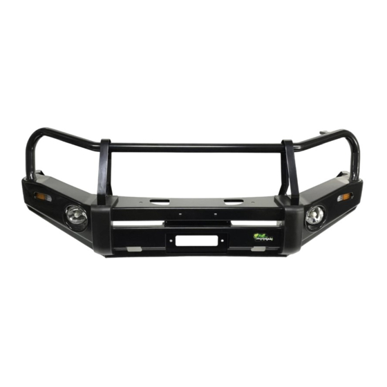
Ironman 4x4 BBC / BBCD / BBA / BBT067-NL / BBT067-SL / BBT067-TL Bull Bars
fit to a Mitsubishi MR Triton 11/2018+
•
It will take about 4 hours to install.
NOTE: This product has been tested for air bag compatibility
and therefore the mounting system MUST NOT be modified
IMPORTANT: Bull bar installations should only be done by a qualified person
©Copyright 2022 Ironman 4x4 Pty Ltd. No part of this publication may be reproduced or replicated without the prior written consent of Ironman 4x4 Pty Ltd
TO SUIT MITSUBISHI MR TRITON 11/2018+
and it's the responsibility of this person to ensure correct fitment.
INSTALLATION
GUIDE
BB067
Advertisement

Related Manuals for Ironman4x4 BB067


Summary of Contents for Ironman4x4 BB067
- Page 1 INSTALLATION GUIDE BB067 TO SUIT MITSUBISHI MR TRITON 11/2018+ • Ironman 4x4 BBC / BBCD / BBA / BBT067-NL / BBT067-SL / BBT067-TL Bull Bars fit to a Mitsubishi MR Triton 11/2018+ • It will take about 4 hours to install.
- Page 2 Installation Guide BB067 Bull Bar Parts List 1. Bull Bar 2. Mounting Bracket QTY-1 QTY-1 3. Steel Skid Plate 4. Steel Skid Plate L-R QTY-1 QTY-2 5. Support Bracket 1 L-R 6. Support Bracket 7. License Plate Bracket 8. Skid Plate Bracket 9.
- Page 3 Installation Guide BB067 Before installation check bull bar application is compatible with your vehicle. Unwrap bull bar. Check over riders and light assemblies are tight in bull bar before installation. Disconnect any bumper lights, sensors and cameras. Remove factory bumper bar, grill assembly and factory protection plate from under radiator.
- Page 4 Installation Guide BB067 Drill holes using a 21mm hole saw, only through outer skin of chassis cross member. Drill a pilot hole using the centre drill bit of the hole saw through the inner skin as shown. Open the inner holes to 12mm Page 4 of 16 ©Copyright 2022 Ironman 4x4 Pty Ltd.
- Page 5 Installation Guide BB067 Mount chassis support brackets to inner and outer faces of chassis using hardware provided. Do not tighten. Use trimmed washer for bolt on inside of tie down point. Insert crush tubes into holes previously drilled in front cross member.
- Page 6 Installation Guide BB067 10. Reinstall mounting cradle to vehicle, centralise, insert and tighten all mounting hardware. 11. If fitting a winch, horns will need to be moved to the rear of the mounting cross member as shown. Page 6 of 16...
- Page 7 Installation Guide BB067 12. Remove grill and lights from bumper bar. Use supplied template to mark both sides of the bumper. Follow the cut line on the OE light recess. Do not cut area mark, “top of light”. The horizontal part of the bumper remains in place, do not cut above the light.
- Page 8 Installation Guide BB067 14. If applicable, fit camera to bull bar through hole located above winch fairlead, using supplied bolts and spacers. 15. Fit bull bar to mounting cradle using supplied M12 bolts, align with vehicle leaving a 10-15mm gap between wings and bumper bar and tighten all bolts.
- Page 9 Installation Guide BB067 18. TO FIT WASHER BOTTLE: Remove battery. Unclip factory wiring loom for washer pump and pull through into engine bay. Cut factory plug off the loom and crimp spade terminals supplied onto the wires. Connect to supplied pump as shown.
- Page 10 Installation Guide BB067 Plastic Parking Sensor Installation IMPORTANT: For parking sensors to function correctly these instructions must be followed closely. Before removing sensors from original bumper bar, note the location and orientation of each sensor so when they are fitted the bullbar this can be duplicated.
- Page 11 Installation Guide BB067 Fit sensor with factory silicone sleeve to the sensor holder and secure using clamping plate and screws provided. Do not over tighten. Clamping plate has a flat side for thicker sensors and a raised section on the other side for thinner sensors.
- Page 12 Installation Guide BB067 Apply adhesion promoter to mounting surfaces around sensor holes and on sensor holders. This step is important to ensure sensor holders adhere properly to the bullbar. Remove protective film from one side of double-sided tape and apply to mounting surface of sensor holder.
- Page 13 Installation Guide BB067 Remove protective film from double-sided tape and apply sensor holder/sensor to bullbar making sure sensors are in the same positions as they were in the original bumper and in the same orientation. Page 13 of 16 ©Copyright 2022 Ironman 4x4 Pty Ltd. No part of this publication may be reproduced or replicated without the prior written consent of Ironman 4x4 Pty Ltd...
-
Page 14: Winch Installation
Installation Guide BB067 Winch Installation 1. Bolt winch to cradle. Bolt fairlead to recess in front of bull bar using bolts, washers and nuts provided. Fit bull bar to vehicle referring to steps of bull bar fitting instructions. Mount control box in desired location. - Page 15 Installation Guide BB067 5. Connect the thin black earth wire and negative battery cable to the earth connection on the opposite side of winch motor. Run the positive and negative battery cables into the engine bay taking care to secure cables away from any sharp or moving objects.
-
Page 16: Wiring Diagrams
Installation Guide BB067 Wiring Diagrams PARK LIGHT & INDICATOR Daytime Running Light Brown Park Light Yellow Indicator Light White Ground If vehicle is not tted with DRL, leave red wire disconnected FOG LIGHTS Ground Lamp Fuse Connector Relay Black Blue...
Need help?
Do you have a question about the BB067 and is the answer not in the manual?
Questions and answers