Table of Contents
Advertisement
Quick Links
––
Camille Bauer Metrawatt AG
Aargauerstrasse 7
CH-5610 Wohlen / Switzerland
Phone: +41 56 618 21 11
Telefax: +41 56 618 35 35
E-Mail: info@cbmag.com
https://www.camillebauer.com
System handbook
Option PME central unit
SINEAX
AM, SINEAX
®
Operating instructions option PME central unit (2023-08)
DM5000, CENTRAX
®
CU, LINAX
PQ
®
®
Advertisement
Table of Contents

Related Manuals for Camille Bauer SINEAX AM


Summary of Contents for Camille Bauer SINEAX AM
- Page 1 DM5000, CENTRAX CU, LINAX ® ® ® ® Operating instructions option PME central unit (2023-08) –– Camille Bauer Metrawatt AG Aargauerstrasse 7 CH-5610 Wohlen / Switzerland Phone: +41 56 618 21 11 Telefax: +41 56 618 35 35 E-Mail: info@cbmag.com https://www.camillebauer.com...
-
Page 2: Legal Information
Legal information Warning notices In this document warning notices are used, which you have to observe to ensure personal safety and to prevent damage to property. Depending on the degree of danger the following symbols are used: If the warning notice is not followed death or severe personal injury will result. -
Page 3: Table Of Contents
Contents Legal information ..............................2 1. Introduction ..............................4 1.1 Purpose of this document .......................... 4 1.2 Scope of supply ............................4 1.3 Further documents............................. 4 2. Safety notes ..............................5 3. Device overview ............................. 5 4. Connection of radio modules ........................7 4.1 General safety notes .......................... -
Page 4: Introduction
1. Introduction 1.1 Purpose of this document This document describes the option PME central unit and the associated radio modules to be used with the devices SINEAX ® AM, SINEAX ® DM5000, CENTRAX ® CU or LINAX ® PQ. It is intended to be used by: •... -
Page 5: Safety Notes
2. Safety notes Device may only be disposed in a professional manner! The installation and commissioning should only be carried out by trained personnel. Check the following points before commissioning: – that the maximum values for all the connections are not exceeded, see "Technical data" section, –... - Page 6 Up to 100 currents, divided between the PME radio modules for 3 or 4 conductors each, can be reliably recorded (AES-128 encryption) without any additional wiring effort. Once a second (default setting), not only the current values are determined from this, but also, thanks to synchronization with the voltage measurement of the base unit, comprehensive performance data and average loads, load profile data and energy meter values are derived, which are also stored as time series in the device.
-
Page 7: Connection Of Radio Modules
4. Connection of radio modules Ensure under all circumstances that the leads are free of potential when connecting them! 4.1 General safety notes Please observe that the data on the type plate must be adhered to! The national provisions have to be observed in the installation and material selection of electric lines, e.g. - Page 8 The Rogowski coils are placed directly around the respective conductors. The current direction, which is indicated by an arrow on the measuring head, must be observed. PM 1002931 000 00 System handbook option PME central unit 8/31...
-
Page 9: Commissioning
5. Commissioning The commissioning of the base unit is described in detail in the respective device handbook. You have to check if the connection data of the device match the data of the plant (see nameplate). If so, you can start to put the device into operation by switching on the power supply and the measurement inputs. -
Page 10: Add A Radio Module To The Base Unit
Powering the module via USB-C (5 VDC) As an alternative to battery power, the module can also be supplied via the side USB-C connector. If possible, use a supply with galvanic isolation. As soon as the module is powered the LED flashes either red or green. - Page 11 If the website is displayed on a device with camera (smart phone, tablet, notebook) or a webcam is connected to the PC, select «Scan QR code», scan the code and proceed to step d). Please note the information on using the camera in appendix If there is no camera available, select •...
-
Page 12: Modifying Module Settings
5.1.3 Modifying module settings The radio modules use default settings, e.g. a transmission power of 0 dBm (1 mW) or a polling interval of 1 s. If radio modules are mounted at a greater distance from the base unit, it may be necessary to increase the transmission power to ensure reliable radio reception. -
Page 13: Installation Check
Detailed information about the state of the PME current modules can be visualized via the service menu: • Name, Serial number, Firmware version and type of the respective module • Battery state of charge [%] • Time since last successful communication •... - Page 14 Energy direction Away from the busbar Towards the busbar b) Installation check for devices with option PME: Phasor diagram and the visualization of sense of rotation and energy direction are displayed in the same image in the instantaneous values menu of the WEB interface.
-
Page 15: Operating The Device
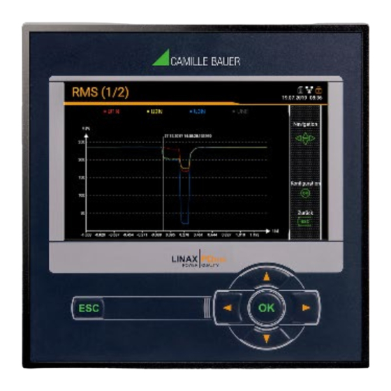
6. Operating the device 6.1 Operating elements PQ1000 /AM1000 PQ3000 / AM2000 / AM3000 PQ5000 / DM5000 The operation of devices with display is performed by means of 6 keys: 4 keys for navigation ( , , , ) and for the selection of values selection ... -
Page 16: Configuration
6.3 Configuration 6.3.1 Local configuration at the device The settings of the optional PME system cannot be viewed or changed locally. 6.3.2 Configuration via web browser All settings for the optional PME system can be made via WEB-GUI. Deviating from the normal functionality of the settings menu, changes to the PME current modules and PME measuring systems during the linking of the modules to the base unit are immediately applied to the current configuration and do not have to be saved explicitly. - Page 17 The mean-value to be displayed can be selected via the corresponding registers. Daily profiles are displayed, together with the values from the previous day. The values for the individual averaging intervals can be read off with the help of a «fly-over»...
- Page 18 Meter content readings in table form Displaying data locally The selection works in principle in the same way as with the WEB-GUI. There are the following differences: • The individual measured quantities are arranged in a display matrix and can be selected via navigation. •...
-
Page 19: Measurement Information In File Format
6.5 Measurement information in file format Using the data export scheduler, measurement information may be provided also in file format. Such files can then: • periodically or event-driven being sent to a SFTP server • locally stored in the device and downloaded via webpage The management and setup of tasks for providing files is done via the item Data export | Data export scheduler in the settings menu. - Page 20 The task list then shows three active tasks. Predefined tasks are marked gray to highlight that they can be deactivated but not removed. On the other hand, at any time the newly created task “PME_data” can be fully modified, deactivated or deleted. Via the settings of the local display only the activation / deactivation of the tasks is supported.
-
Page 21: Accessing File Information Via Webpage
6.5.3 Accessing file information via webpage You can access files stored in the device using the service menu Local data storage | Download data. Depending on the tasks defined in the data export scheduler the available file structure may be different: •... -
Page 22: Technical Data
8. Technical data Current module CTR75-1000A Number of channels 3 or 4 Max. number of modules 25...33 (≤100 currents per PME central unit) Frequency range 10 Hz up to 100 kHz Max. rated current I 1000 A Max. measurable current 1,2 x I Starting current 2 A (fundamental component) -
Page 23: Annex
Annex A Description of measured quantities of the PME measurement systems Used abbreviations 2LN 3-wire load in a split phase system (system with 2 phases and center tap), with neutral current measurement 3-phase load, unbalanced load 4-wire load, unbalanced load, without neutral current measurement 4LN 4-wire load, unbalanced load, with neutral current measurement A1 Basic measurements The acquisition of the currents by means of the radio modules is synchronized to the voltages of the base... -
Page 24: A2 Harmonic Analysis
A2 Harmonic analysis Measurement THD Current I1 √ √ √ √ √ √ √ √ THD Current I2 THD Current I3 √ √ √ THD Current IN √ √ TDD Current I1 √ √ √ √ TDD Current I2 √ √... -
Page 25: A3 Mean-Values With Fluctuation Range
A3 Mean-values with fluctuation range The interval time can be selected in the range from 1 minute to two hours. The internal clock is used to synchronize the averaging intervals. The maximum and minimum RMS values are also determined for the interval Measurement Current I1 ●... -
Page 26: A4 Meters
A4 Meters The subsequent energy meter contents are provided for each PME measurement system. Measured quantity Active energy I+IV Active energy II+III Reactive energy I+II Reactive energy III+IV Programmable meter resolution For all meters the resolution (displayed unit) can be selected almost freely. This way, applications with short measurement times, e.g. -
Page 27: B Display Matrix Pme Measurement Systems
B Display matrix PME measurement systems (CTR1) (CTR 2) (CTR 3) ..(CTR 25…33) PHASOR_PME INST_UI INST_PQS INST_SYS PHASE_SEQ PM 1002931 000 00 System handbook option PME central unit 27/31... -
Page 28: C Using A Camera
C Using a camera In order to be able to use the camera to scan the QR code on a website, the following points must be observed: • The website must use secure HTTPS communication. Note: Enabling web security using HTTPS is described in the device manual for the basic device. - Page 29 • Depending on the browser, a permission may be required before activating the camera. Browser: Firefox • Permission to use the camera via a website can be revoked at any time. If several cameras are connected, the camera to be used can be selected Browser: Chrome PM 1002931 000 00 System handbook option PME central unit...
-
Page 30: D Radio Compliance Statement
(2) l'utilisateur de l'appareil doit accepter tout brouillage radioélectrique subi, même si lebrouillage est susceptible d'en compromettre le fonctionnement.” Camille Bauer Metrawatt AG is not responsible for any radio television interference caused by unauthorized modifications of this equipment or the substitution or attachment of connecting cables and equipment other than those specified by Camille Bauer Metrawatt AG. -
Page 31: Index
INDEX Camera usage ............28 Measurements ............23 Commissioning ............9 Basic quantities ..........23 Configuration Harmonic analysis ..........24 Menu ..............16 Mean-values ............. 25 cosφ ..............23, 25 Meters ............... 26 Meter resolution ............ 26 Device overview ............5 Operating elements ..........
Need help?
Do you have a question about the SINEAX AM and is the answer not in the manual?
Questions and answers