Table of Contents
Advertisement
Available languages
Available languages
Quick Links
Camille Bauer AG
Aargauerstrasse 7
CH-5610 Wohlen/Switzerland
Telefon +41 56 618 21 11
Telefax +41 56 618 35 35
e-mail: info@camillebauer.com
http://www.camillebauer.com
Betriebsanleitung SINEAX DME 400
Mode d'emploi SINEAX DME 400
Operating Instructions SINEAX DME 400
DME 400-1 Bd-f-e
DME400, Industrial/Commercial, TP/FT-10
3-Phase Power Meter, model number 01
127 119-03
09.09
1
Advertisement
Chapters
Table of Contents

Related Manuals for Camille Bauer SINEAX DME 400 Series


Summary of Contents for Camille Bauer SINEAX DME 400 Series
- Page 1 Operating Instructions SINEAX DME 400 DME 400-1 Bd-f-e 127 119-03 09.09 DME400, Industrial/Commercial, TP/FT-10 3-Phase Power Meter, model number 01 Camille Bauer AG Aargauerstrasse 7 CH-5610 Wohlen/Switzerland Telefon +41 56 618 21 11 Telefax +41 56 618 35 35 e-mail: info@camillebauer.com...
- Page 3 Betriebsanleitung Programmierbarer Multi-Messumformer ® mit L Interface ORKS SINEAX DME 400 ........4 Mode d’emploi Convertisseur de mesure multiple ® programmable avec interface L ORKS SINEAX DME 400 ........20 Operating Instructions Programmable multi-transducer with ® Interface ORKS SINEAX DME 400 ........36 Geräte dürfen nur fachgerecht entsorgt werden! Les appareils ne peuvent être éliminés que de façon appropriée! The instruments must only be disposed of in the correct way!
-
Page 4: Table Of Contents
03.06 1. Erst lesen, dann … ............. 4 DME400, Industrial/Commercial, TP/FT-10 3-Phase Power Meter, model number 01 2. Lieferumfang ............... 4 Camille Bauer AG Aargauerstrasse 7 CH-5610 Wohlen/Switzerland Telefon +41 56 618 21 11 3. Kurzbeschreibung ............4 Telefax +41 56 61835 35 e-mail: info@camillebauer.com... -
Page 5: Bestellangaben
4. Bestellangaben Eigenverbrauch [VA] (bei externer MERKMAL KENNUNG Hilfsenergie): Spannungspfad: U / 400 kΩ 1. Bauform 400 - 1 Strompfad: ≤ I · 0,01 Ω Gehäuse T24 für Schienen- und Wand- Montage Zulässige dauernd überhöhte Eingangsgrössen 2. Nennfrequenz 50 Hz (60 Hz möglich ohne Zusatz- Strompfad 10 A bei 400 V fehler;... - Page 6 Anzahl Knoten in Hilfsenergie einem Domain: Max. 32'385 (127 × 255) Spannung: Gemäss Angabe auf dem Typen- Busabschluss: Extern schild 90…110 V = 100 V Anschlüsse: Schraubanschluss Klemmen 99…121 V = 110 V 15 und 16 AC 207…253 V = 230 V Interface ORKS ®...
-
Page 7: Messgrössen, Die Über Lon Works ® Interface Zur Verfügung Stehen
5.1 Messgrössen, die über L ® Interface zur Verfügung stehen ORKS Tabelle 1: Anwendung Anwendung (siehe Tabelle 4) (siehe Tabelle 4) Sym- Sym- Erklärungen Erklärungen bole A24 / bole A24 / … … ● Eingangsspannung –– –– ● ● ● Frequenz der ●... -
Page 8: Zurücksetzen
5.3 Programmierung des SINEAX DME 400 5.2 Zurücksetzen – Reset der Energiezähler Der SINEAX DME 400 lässt sich auf zwei Arten program- – Reset der Schleppzeiger mieren: 1) über RS 232, mit PC Software 2) über L ® Interface ORKS mit L ®... - Page 9 Fortsetzung der «Tabelle 2: Programmierung» Anwendung MERKMAL A11 … A16 A24 / A44 5. Energiezähler 1 Nicht belegt EA00 EA00 EA00 Netz [Wh] EA50 ––– ––– [Wh] ––– EA51 EA51 [Wh] ––– EA52 EA52 [Wh] ––– EA53 EA53 Netz [Wh] EA54 EA54 EA54...
-
Page 10: Dateien Für Installations-Tools
5.4 Dateien für Installations-Tools Defi nierte UCPT’s CB_UC01.TYP Binary defi nitions of user types Gerätebeschreibung CB_UC01.ENM Binary defi nitions of user DME400.XIF External Interface File enumerations CB_UC01.FMT ASCII defi nition of user formats 5.5 Benutzerdefi nierte Konfi gurationsparameter (UCPT’s) (Tabelle 3) Confi... -
Page 11: Standard Netzwerk Variablen (Snvt's) (Tabelle 4)
Confi guration UCPT Name Range Description Property Index energy UCPT_energy_IND 36: APPARSY_PWR energy of the apparent power of the system index 37: APPAR01_PWR energy of the apparent power of phase 1 38: APPAR02_PWR energy of the apparent power of phase 2 39: APPAR03_PWR energy of the apparent power of phase 3 152: TRUESY_PWR_OUT... - Page 12 Anwendung Objekt- Name Beschreibung A11, A13 A15, A16 ● ● nvo_AmpB1_Value SNVT_amp_f –– RMS-Wert des Stromes Phase 1 (bimetal), 15 min. ● ● nvo_AmpB2_Value SNVT_amp_f –– RMS-Wert des Stromes Phase 2 (bimetal), 15 min. ● ● nvo_AmpB3_Value SNVT_amp_f –– RMS-Wert des Stromes Phase 3 (bimetal), 15 min.
-
Page 13: Befestigung
Anwendung Objekt- Name Beschreibung A11, A13 A15, A16 ● nvo_React01_Fact SNVT_pwr_fact_f –– –– Blindfaktor Strang 1 (Aussenleiter L1 und Sternpunkt N) ● nvo_React02_Fact SNVT_pwr_fact_f –– –– Blindfaktor Strang 2 (Aussenleiter L2 und Sternpunkt N) ● nvo_React03_Fact SNVT_pwr_fact_f –– –– Blindfaktor Strang 3 (Aussenleiter L3 und Sternpunkt N) ●... -
Page 14: Elektrische Anschlüsse
7. Elektrische Anschlüsse ORKS ® Wink Service- Funktion Anschluss Interface Messeingang Wechselstrom 1 / 3 4 / 6 7 / 9 Front- Wechselspannung UL1 seite ORKS ® Interface RS 232 Wink Service-Pin Hilfsenergie AC – Bei Hilfsenergie ab Spannungseingang erfolgt der interne Anschluss wie folgt: Anwendung (Netzform) Anschluss intern... - Page 15 Messeingänge Netzformen / Klemmenbelegung Anwendung Dreileiter- Drehstromnetz gleichbelastet I: L1 Bei Strommessung über L2 bzw. L3, Spannungsanschluss nach folgender Tabelle vornehmen: Stromwandler Klemmen Dreileiter- Drehstromnetz gleichbelastet Kunstschaltung U: L1 – L2 I: L1 Bei Strommessung über L2 bzw. L3, Spannungsanschluss nach folgender Tabelle vornehmen: Stromwandler Klemmen Dreileiter-...
- Page 16 Messeingänge Netzformen / Klemmenbelegung Anwendung Dreileiter- Drehstromnetz gleichbelastet Kunstschaltung U: L2 – L3 I: L1 Bei Strommessung über L2 bzw. L3, Spannungsanschluss nach folgender Tabelle vornehmen: Stromwandler Klemmen Vierleiter- Drehstromnetz gleichbelastet I: L1 Bei Strommessung über L2 bzw. L3, Spannungsanschluss nach folgender Tabelle vornehmen: Stromwandler Klemmen Dreileiter-...
- Page 17 Messeingänge Netzformen / Klemmenbelegung Anwendung Vierleiter- Drehstromnetz ungleich- belastet 3 einpolig isolierte Spannungswandler im Hochspannungsnetz 9 11 Vierleiter- Drehstromnetz ungleich- belastet, Open-Y- Schaltung 2 einpolig isolierte Spannungswandler im Hochspannungsnetz Niederspannungsnetz Unterscheidung von PF, QF und LF Ausgang kap. ind. kap. ind.
-
Page 18: Inbetriebnahme
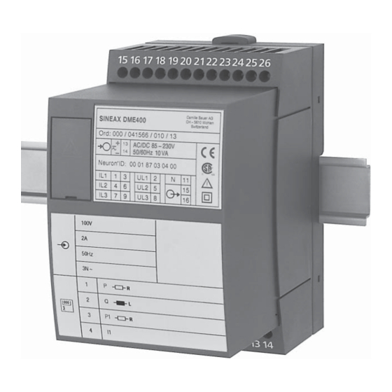
Vor der Inbetriebnahme überprüfen, ob die Anschlussdaten des Messumformers mit den Daten der Anlage übereinstimmen (siehe Typenschild). Danach kann der Messumformer in Betrieb genommen werden. Camille Bauer AG SINEAX DME 400 CH - 5610 Wohlen Switzerland Ord: 400/400400/400/1 AC/DC 85…230 V... -
Page 19: Sicherheitshinweise
Bedeutung der Symbole auf dem Gerät 12. Sicherheitshinweise Die Symbole auf dem Gerät haben folgende Bedeutung: ● Bevor das Gerät in Betrieb genommen wird, muss ge- prüft werden, für welche Hilfsenergiespannung das Gerät gebaut ist. ● Überzeugen Sie sich, dass die Anschlussleitungen nicht beschädigt und während der Verdrahtung des Gerätes Warnung vor einer Gefahrenstelle spannungsfrei sind. -
Page 20: A Lire En Premier, Ensuite
1. A lire en premier, ensuite … ........20 DME400, Industrial/Commercial, TP/FT-10 3-Phase Power Meter, model number 01 2. Etendue de la livraison ..........20 Camille Bauer AG Aargauerstrasse 7 CH-5610 Wohlen/Switzerland Telefon +41 56 618 21 11 Telefax +41 56 61835 35 3. -
Page 21: Références De Commande
4. Références de commande Consommation propre [VA] (en alimentation CARACTERISTIQUE DESIGNATION auxiliaire externe): Circuit de tension: U / 400 kΩ Circuit d’intensité: ≤ I · 0,01 Ω 1. Construction 400 - 1 Boîtier T24 pour montage sur rail ou Augmentation permanente admissible des grandeurs sur paroi d’entrée 2. - Page 22 Nombre de nœuds Alimentation auxiliaire dans un domaine: Max. 32'385 (127 × 255) Tension: Selon plaquette signalétique Bouclage du bus: Externe 90…110 V = 100 V 99…121 V = 110 V Connexions: Bornes à visser 15 et 16 CA 207…253 V = 230 V Interface CA 360…440 V...
- Page 23 5.1 5.1 Grandeurs de mesure disponibles par l’interface L ® ORKS Tableau 1 1: Application Application (voir tableau 4) Sym- Signifi cation (voir tableau 4) bole Sym- A24 / … Signifi cation bole A24 / … ● ● ● Fréquence de la grandeur ●...
-
Page 24: Remise À Zéro
5.3 Programmation du SINEAX DME 400 5.2 Remise à zéro – Remise à zéro des compteurs d’énergie La programmation du SINEAX DME 400 peut être réalisée – Remise à zéro de la fonction d’aiguille entraînée de deux façons différentes: 1) par RS 232, avec logiciel PC 2) par l’interface L ®... - Page 25 Suite du «Tableau 2: Programmation» Application CARACTERISTIQUE A11 … A16 A24 / A44 5. Compteur d’énergie 1 Non utilisé EA00 EA00 EA00 Réseau [Wh] EA50 ––– ––– [Wh] ––– EA51 EA51 [Wh] ––– EA52 EA52 [Wh] ––– EA53 EA53 Réseau [Wh] EA54 EA54...
-
Page 26: Fichiers
5.4 Fichiers Paramètres UCPT pour outil d’installation CB_UC01.TYP Binary defi nitions of user types Description pour outil d’installation CB_UC01.ENM Binary defi nitions of user DME400.XIF External Interface File enumerations CB_UC01.FMT ASCII defi nition of user formats 5.5 Paramètres de confi guration défi nis par l’utilisateur (UCPT’s) (Tableau 3) Confi... -
Page 27: Variables Standard Du Réseau (Snvt's) (Tableau 4)
Confi guration UCPT Name Range Description Property Index energy UCPT_energy_IND 36: APPARSY_PWR energy of the apparent power of the system index 37: APPAR01_PWR energy of the apparent power of phase 1 38: APPAR02_PWR energy of the apparent power of phase 2 39: APPAR03_PWR energy of the apparent power of phase 3 152: TRUESY_PWR_OUT... - Page 28 Application Object Type A11, A13 Description A15, A16 ● ● nvo_AmpB1_Value SNVT_amp_f –– Valeur effective de l’intensité phase 1 (bilame), 15 min. ● ● nvo_AmpB2_Value SNVT_amp_f –– Valeur effective de l’intensité phase 2 (bilame), 15 min. ● ● nvo_AmpB3_Value SNVT_amp_f ––...
-
Page 29: Fixation
Application Object Type Description A11, A13 A15, A16 ● nvo_React01_Fact SNVT_pwr_fact_f –– –– Facteur réactif, branche 1 (phase externe L1 et point neutre N) ● nvo_React02_Fact SNVT_pwr_fact_f –– –– Facteur réactif, branche 2 (phase externe L2 et point neutre N) ●... -
Page 30: Raccordements Électriques
7. Raccordements électriques Wink Pin de Interface Fonction Connexion ORKS ® service Entrée de Courant alternatif 1 / 3 mesure 4 / 6 7 / 9 Face Tension alternative UL1 avant ORKS ® Interface L RS 232 Wink Pin de service Alimentation CA auxiliaire –... - Page 31 Entrées de mesure Réseau / Disposition des bornes Application Courant triphasé 3 fils à charges équilibrées I: L1 Pour la mesure du courant en L2 resp. L3, connecter les tensions selon tableau ci-après: Transformateur Bornes de courant Courant triphasé 3 fils à...
- Page 32 Entrées de mesure Réseau / Disposition des bornes Application Courant triphasé 3 fils à charges équilibrées Phase artificielle Pour la mesure du courant en L2 resp. L3, connecter les tensions selon tableau ci-après: U: L2 – L3 I: L1 Transformateur Bornes de courant Courant...
- Page 33 Entrées de mesure Réseau / Disposition des bornes Application Courant triphasé 4 fils à charges dés- équilibrées 3 transformateurs de tensions unipolaires isolés pour réseau haute tension 9 11 Courant triphasé 4 fils à charges dés- équilibrées Open-Y- connection 2 transformateurs de tensions unipolaires isolés pour réseau haute tension Réseau basse tension Détermination de PF, QF et LF...
-
Page 34: Mise En Service
(voir plaquette signalétique). Ensuite, le convertisseur de mesure peut être mise en service. Camille Bauer AG SINEAX DME 400 CH - 5610 Wohlen Switzerland Ord: 400/400400/400/1 AC/DC 85…230 V 50/60 Hz 10 VA Fig. -
Page 35: Consignes De Sécurité
Signifi cation des symboles fi gurant sur l’appareil 12. Consignes de sécurité Les symboles fi gurant sur l’appareil signifi ent: ● Avant de mettre l’appareil en service, vérifi er pour quelle tension d’alimentation auxiliaire il a été conçu. ● S’assurer que les câbles de connexion ne soient pas endommagés et qu’ils soient sans tension lors du rac- cordement de l’appareil. -
Page 36: Read Fi Rst And Then
03.06 2. Scope of supply ............36 DME400, Industrial/Commercial, TP/FT-10 3-Phase Power Meter, model number 01 3. Brief description ............36 Camille Bauer AG Aargauerstrasse 7 CH-5610 Wohlen/Switzerland Telefon +41 56 618 21 11 Telefax +41 56 61835 35 4. Ordering information ..........37 e-mail: info@camillebauer.com... -
Page 37: Ordering Information
4. Ordering information Consumption [VA] (at external DESCRIPTION MARKING power supply): Voltage circuit: U / 400 kΩ Current circuit: ≤ I · 0.01 Ω 1. Mechanical design 400 - 1 Housing T24 for rail and wall mounting 2. Rated frequency 50 Hz (60 Hz possible without additional error;... - Page 38 Number of nodes Power supply per domain: Max. 32'385 (127 × 255) Voltage: According to type label Bus termination: External 90…110 V = 100 V 99…121 V = 110 V Terminals: Screw terminals, AC 207…253 V = 230 V terminals 15 and 16 AC 360…440 V = 400 V Interface...
-
Page 39: Measurands Available Via Lon Works ® Interface
5.1 Measurands available via L ® Interface ORKS Table 1: Application Application (see table 4) (see table 4) Sym- Sym- Meaning Meaning bols A24 / bols A24 / … … ● Input voltage –– –– ● ● ● Frequency of the input variable ●... -
Page 40: Resetting
5.3 Programming the SINEAX DME 400 5.2 Resetting – Energy meter reset There are two ways to confi gure the SINEAX DME 400: – Maximum value pointer reset 1) via RS 232, with PC software ® 2) via L Interface ORKS with L ®... - Page 41 Continuation “Table 2: Programming” Application DESCRIPTION A11 … A16 A24 / A44 5. Energy meter 1 Not used EA00 EA00 EA00 System [Wh] EA50 ––– ––– [Wh] ––– EA51 EA51 [Wh] ––– EA52 EA52 [Wh] ––– EA53 EA53 System [Wh] EA54 EA54 EA54...
-
Page 42: Files
5.4 Files The fi les used for the installation tools are: CB_UC01.TYP Binary defi nitions of user types Description for the installation tools: CB_UC01.ENM Binary defi nitions of user DME400.XIF External Interface File enumerations CB_UC01.FMT ASCII defi nition of user formats 5.5 User-defi... -
Page 43: Standard Network Variables Types (Snvt's) (Table 4)
Confi guration UCPT Name Range Description Property Index energy UCPT_energy_IND 36: APPARSY_PWR energy of the apparent power of the system index 37: APPAR01_PWR energy of the apparent power of phase 1 38: APPAR02_PWR energy of the apparent power of phase 2 39: APPAR03_PWR energy of the apparent power of phase 3 152: TRUESY_PWR_OUT... - Page 44 Application Object Name Type Description A11, A13 A15, A16 ● ● nvo_AmpB1_Value SNVT_amp_f –– RMS value of the current phase 1 (bimetal), 15 min. ● ● nvo_AmpB2_Value SNVT_amp_f –– RMS value of the current phase 2 (bimetal), 15 min. ● ●...
-
Page 45: Mounting
Application Object Name Type Description A11, A13 A15, A16 ● ● ● nvo_ReactSY_Fact SNVT_pwr_fact_f Reactive power factor of the system ● nvo_React01_Fact SNVT_pwr_fact_f –– –– Reactive power, phase 1 (phase-to-neutral L1 – N) ● nvo_React02_Fact SNVT_pwr_fact_f –– –– Reactive power, phase 2 (phase-to-neutral L2 –... -
Page 46: Electrical Connections
7. Electrical connections ORKS ® Signal Service Function Connection Interface Measuring input AC current IL1 1 / 3 4 / 6 7 / 9 Front AC voltage UL1 ORKS ® Interface RS 232 Signal Service pin Power supply – If power supply is taken from the measured voltage internal connections are as follow: Application (system) Internal connection... - Page 47 Measuring inputs System / Terminals application 3-wire 3-phase symmetric load I: L1 Connect the voltage according to the following table for current measurement in L2 or L3: Current transf. Terminals 3-wire 3-phase symmetric load phase-shift U: L1 – L2 I: L1 Connect the voltage according to the following table for current measurement in L2 or L3: Current transf.
- Page 48 Measuring inputs System / Terminals application 3-wire 3-phase symmetric load phase-shift U: L2 – L3 I: L1 Connect the voltage according to the following table for current measurement in L2 or L3: Current transf. Terminals 4-wire 3-phase symmetric load I: L1 Connect the voltage according to the following table for current measurement in L2 or L3: Current transf.
- Page 49 Measuring inputs System / Terminals application 4-wire 3-phase asymmetric load 3 single-pole insulated voltage transformers in high-voltage system 9 11 4-wire 3-phase asymmetric load, Open Y connection 2 single-pole insulated voltage transformers in high-voltage system Low-voltage system Difference between PF, QF and LF Output cap.
-
Page 50: Commissioning
(see type label). The power supply to the transducer can then be switched on and the signals applied to the measuring inputs. Camille Bauer AG SINEAX DME 400 CH - 5610 Wohlen Switzerland Ord: 400/400400/400/1 AC/DC 85…230 V... -
Page 51: Safety Notes
Meaning of the symbols on the device 12. Safety notes The symbols on the device have the following meaning: ● Before you start the device check for which power supply it is built. ● Verify that the connection leads are in good condition and that they are electrically dead while wiring the device.
Need help?
Do you have a question about the SINEAX DME 400 Series and is the answer not in the manual?
Questions and answers