Table of Contents
Advertisement
Quick Links
Advertisement
Table of Contents

Related Manuals for Camille Bauer Sineax Cam


Summary of Contents for Camille Bauer Sineax Cam
-
Page 1: Operating Instructions
Operating instructions Graphic display for SINEAX CAM CAM Display Be 156 861-01 06.10 Camille Bauer AG Aargauerstrasse 7 CH-5610 Wohlen / Switzerland Phone +41 56 618 21 11 Fax +41 56 618 35 35 e-mail: info@camillebauer.com http://www.camillebauer.com... -
Page 3: Table Of Contents
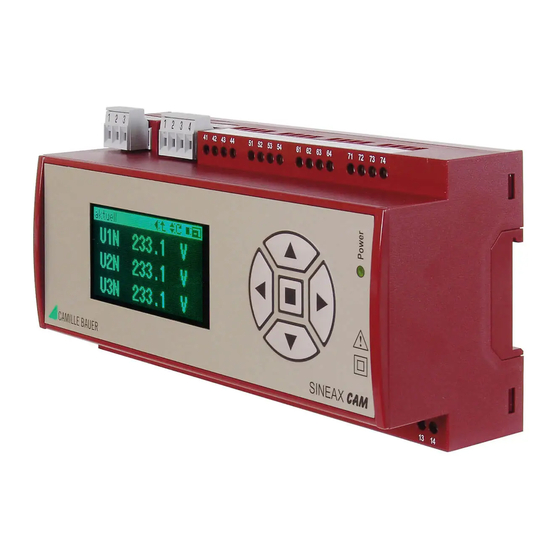
The optional graphic display is intended for on-site visualization of measurement data, lists and alarms of the SINEAX CAM. The operation of the display is performed by means of the keys. Using the keys the user may acknowledge alarms or extreme values as well. Which data can be displayed depends on the version of the device, especially which I/O modules are present and which options are activated. -
Page 4: Display Structure And Operation
1. Display structure and operation Generally When first switching on the device the main When changing the display window menu is displayed. On every further start-up the there may be a waiting time, which is last displayed image before the power-down is symbolized by displaying a sand shown. -
Page 5: Settings
2. Settings select a parameter group Invoke the line settings in the main menu. This line will be visible only if the selection is shifted downwards. In the menu settings go to the line with the desired parameter group using the keys . -
Page 6: Settings Of The Clock
2.3 Settings of the clock The SINEAX CAM has an internal clock, which To handle this problem the SINEAX CAM uses is used as a time reference for alarms, events, internally UTC time only (see below). The user progression of measurements and so on. Due... -
Page 7: Security System
3. Security system The device supports a security system which For the display the following functions may be allows to selectively assign rights to different protected using the security system: users. Thereby rights for the changing of - Reset of meters and extreme values measurement or configuration data or the - Settings of display, interface and clock simulation of I/O data may be granted. -
Page 8: Display Measurements
4. Display measurements The Measurements menu has more entries as directly can be displayed. Via main menu the menu measurements may Meters: All acquired meter contents of the be invoked. There the following data are measured system and the I/O's. available: I/O, relays: Measurements resp. -
Page 9: Measurement Display Of System Quantities
4.2 Measurement display of system quantities Present: Contains the instantaneous values of the system Minimum, maximum: Shows all acquired minimum and maximum values with timestamp Reset minimum, maximum: Allows to selectively reset the acquired extreme values Present This predefined assembling of measurements consists of multiple pages. -
Page 10: Measurement Display Of Harmonics
4.3 Measurement display of harmonics Present: Contains the present harmonic contents as well as THD and TDD Maximum: Contains the acquired maximum values with timestamp Reset maximum: Allows to selectively reset the maximum values Present Each page shows a graphical overview of the present harmonic contents (U or I) and the value for one individual harmonic. -
Page 11: Display Meter Contents
4.4 Display meter contents Meter contents are acquired for both the measured system as well as for analog inputs. For digital inputs it takes place only if the inputs are configured as meter inputs. Meters For each meter the contents for high tariff (HT) and for low tariff (LT) are displayed. -
Page 12: Measurement Display Of Mean Values
4.6 Measurement display of mean values Mean values may be acquired with two measurement displays are variable. Up to 12 different interval times t1 and t2. The different pages may be displayed. The selection corresponding measured quantities are freely is performed using the keys configurable. -
Page 13: Measurements For Wiring Control
4.7 Measurements for wiring control The wiring check shows measurements for voltage and current of all phases and the direction of energy flow of the currents. If all voltages have almost similar values and the energy flow direction of the currents is equal it may be assumed that the wiring has been performed correctly. -
Page 14: Alarms
5. Alarms Via the logic module of the SINEAX CAM The acknowledgement resets a possibly complex contexts may be monitored. Out of defined further action, e.g. the switching of a them alarms can be generated, which are relay output. The alarm handling is possible... -
Page 15: Lists
6. Lists The option Lists allows to perform a All recordings can be displayed on request, with chronological recording of events, alarms or time stamp and dedicated text. If the security system messages. At a later time it's possible system has been activated for specific displays to understand and analyse each state also the involved user is available. - Page 16 Operator list This list contains all the events which are The monitored events are listed below. All texts caused by a user interaction or a specific are predefined and can't be modified by the system event. user. list entry The time stamp shows the time of the occurrence of the event.
- Page 17 Alarm handling - Acknowledgement of all active alarms - Selective alarm acknowledgement LS1..16, with detail code (binary) - Selective alarm acknowledgement LS17..32, with detail code (binary) Reset - Standard meters - Meters of the module inputs - min./max. of instantaneous values with detail code (binary) - min./max.
-
Page 18: Logger
7. Logger Via display the status of the logger can be The optional Logger serves for long-term recordings of measurement progressions. requested. This way it's possible to make an assumption how long the corresponding data The user can record variations of recording can continue. -
Page 19: Menu Overview
8. Menu overview structure and operation: page 4 page 8 page 14 page 9 page 15 page 10 page 18 page 7 page 11 page 5 page 11 page 12 page 13...
Need help?
Do you have a question about the Sineax Cam and is the answer not in the manual?
Questions and answers