Table of Contents
Advertisement
Quick Links
Advertisement
Table of Contents

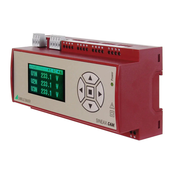
Summary of Contents for Camille Bauer SINEAX CAM
- Page 1 Operating Instructions Universal measuring unit for heavy current variables SINEAX CAM CAM Be 156 481-12 09.10 Camille Bauer Ltd. Aargauerstrasse 7 CH-5610 Wohlen/Switzerland Phone +41 56 618 21 11 Fax +41 56 618 35 35 info@camillebauer.com www.camillebauer.com...
-
Page 2: Table Of Contents
Operating Instructions Universal measuring unit for heavy current variables SINEAX CAM 2. Scope of supply Obligatory safety instructions are marked with the following symbols in these directions: SINEAX CAM (1) 1 Safety instructions (2) 1 Software and documentation CD (3) -
Page 3: Releasing
Snap housing on the top-hat rail (EN 50 022) (see Fig. 1). Digital outputs 12/24 V DC Rel. 24 V x = 4..7 x2 x3 x4 – C2 C3 22 kΩ Counter i = 1..4 I/O i: Digital I/O Fig. 1. Mounting on top-hat rail 35 x 15 or 35 x 7.5 mm. 1) Recommended if input resistance >... - Page 4 Connection modes Network / Terminal arrangement application All voltage measurement inputs must originate at circuit breakers or fuses rated 10 Amps 2 11 or less. This does not apply to the neutral connector. You have to provide a method for manually removing power from the device, such as a clearly labeled circuit breaker or a fused disconnect switch.
- Page 5 Network / Network / Terminal arrangement Terminal arrangement application application 11 1 9 10 12 Three-wire three-phase system asymmetri- cal load Aron 9 10 12 measuring circuit Four-wire three-phase system asymmetri- cal load Open Y 11 1 9 10 12 circuit 9 10 11 12...
-
Page 6: Interface
5.2 Interface RS485 bus connection (Modbus) The terminals (1, 2, 3) are galvanically isolated from the CAM. have resistors are e.g. W&T13601 (PC print), and W&T86201 The signal wires (1, 2) must be twisted. The GND (3) can be converter from Wiesemann & Theis GmbH). connected with a wire or the cable screen. -
Page 7: Software Installation
SINEAX CAM responds to input devices The complete confi guration of the device is devided in subjects the right way. -
Page 8: Protecting Devices
(sinusoidal) all necessary information is summarized in the document Consumption: ≤ U / 3 MΩ per phase “SINEAX CAM Modbus interface”. This may be found on the CD as well. Input impedance: 3 MΩ per phase Thermal ratings: 480 V... - Page 9 Infl uence quantities and permissible variations Basic measurement quantities According to IEC / EN 60 688 : FS: Maximum value of the input confi guration Measured quantity (Full Scale) : FS: FS-Voltage x FS-Current ✓ ✓ ✓ Voltage • • • ✓...
-
Page 10: I/O-Interface
7.2 I/O-Interface Input current < 2.5 mA Counting frequency (S0) ≤ 50 Hz Relay (Terminals 21-23, 31-33) Logical ZERO – 6 till + 20 V Number: Logical ONE 30 till 157 V Contacts: Changeover contact Switching limit Approx. 25 V / 0.8 mA Load capacity: 250 V AC, 2 A, 500 VA 30 V DC, 2 A, 60 W... -
Page 11: Logger And Lists (Optional)
Response time 40ms + 17ms + 0ms + 30ms = 87ms Internal clock (RTC) Function: Time reference, Counter for opera- Ambient conditions, general information ting hours Operating temperature: – 10 till 15 till 30 till 55 °C Accuracy: ± 2 Minutes/Month (15 till 30°C) trimmable via PC-Software Storage temperature: –... -
Page 12: Maintenance
software. Due to the high degree of freedom for the confi - 11. Declaration of conformity guration of logger and lists no general information about the maximal storage duration can be given. But these can be seen in the software when selecting the memory allocation, EG - KONFORMITÄTSERKLÄRUNG DECLARATION OF CONFORMITY the measurands to store and the number of list entries.


Need help?
Do you have a question about the SINEAX CAM and is the answer not in the manual?
Questions and answers