Table of Contents
Advertisement
Quick Links
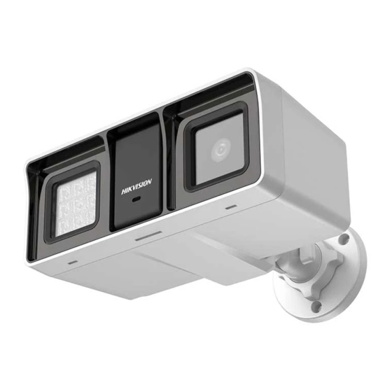
Smart Hybrid Light Audio Fixed
Bullet Camera
User Manual
User Manual
Thank you for purchasing our product. If there are any
questions, or requests, do not hesitate to contact the
dealer.
This manual applies to the models below:
Model
DS-2CE18D0T-LFS
DS-2CE18K0T-LFS
This manual may contain several technical mistakes or
printing errors, and the content is subject to change
without notice. The updates will be added to the new
version of this manual. We will readily improve or update
the products or procedures described in the manual.
01000020231226
Advertisement
Table of Contents

Subscribe to Our Youtube Channel
Related Manuals for HIKVISION DS-2CE18D0T-LFS


Summary of Contents for HIKVISION DS-2CE18D0T-LFS
- Page 1 This manual applies to the models below: Model DS-2CE18D0T-LFS DS-2CE18K0T-LFS This manual may contain several technical mistakes or printing errors, and the content is subject to change without notice. The updates will be added to the new version of this manual.
-
Page 2: About This Document
Any part of the Document, including text, pictures, graphics, etc., belongs to Hikvision. No part of this Document may be excerpted, copied, translated, or modified in whole or in part by any means without written permission. -
Page 3: Regulatory Information
IN THE EVENT OF ANY CONFLICTS BETWEEN THIS DOCUMENT AND THE APPLICABLE LAW, THE LATTER PREVAILS. © Hangzhou Hikvision Digital Technology Co., Ltd. All rights reserved. Regulatory Information EU Compliance Statement This product and - if applicable - the supplied accessories too are marked with "CE"... - Page 4 These instructions are intended to ensure that user can use the product correctly to avoid danger or property loss. The precaution measure is divided into “Warnings” and “Cautions”. Warnings: Serious injury or death may occur if any of the warnings are neglected. Cautions: Injury or equipment damage may occur if any of the cautions are neglected.
-
Page 5: Product Features
The sensor may be burned out by a laser beam, so when any laser equipment is in using, make sure that the surface of sensor will not be exposed to the laser beam. Do not expose the device to high electromagnetic ... - Page 6 If the product does not function properly, contact your dealer or the nearest service center. DO NOT disassemble the camera for repair or maintenance by yourself. Installation of Camera 2.1.1 Ceiling/Wall Mounting Steps: 1. Paste the drill template (supplied) to the installation location.
- Page 7 Figure 2-4 Secure the Junction Box on the Wall 7. Route the cables through the bottom cable hole or side cable hole of the junction box and connect the cables. 8. Fix the junction box cover on its body with three PM3 ×...
-
Page 8: Menu Description
Secure Main Body to Wall Figure 2-8 5. (Optional) Drill the cable hole, when the cables are routed through the wall. 6. Secure the camera to the cover of the wall mount with three PM4 × 13 screws and three M4 screws. Figure 2-9 Secure Camera to Wall Mount Cover 7. - Page 9 Steps: 1. Connect the camera with the TVI DVR and the monitor, as shown in figure 3-1. Figure 3-1 Connection 2. Power on the camera, TVI DVR, and monitor to view the image on the monitor. 3. Click PTZ Control to enter the PTZ Control interface. 4.
-
Page 10: Video Format
3.1 VIDEO FORMAT Model Video Output Video Format 2 MP@25 fps DS-2CE18D0T- TVI, AHD, CVI, 2 MP@30 fps CVBS NTSC 3K@20 fps 4 MP@25 fps 4 MP@30 fps 2 MP@25 fps 2 MP@30 fps DS-2CE18K0T- 5 MP@20 fps 4 MP@25 fps 4 MP@30 fps 4 MP@25 fps 4 MP@30 fps... -
Page 11: Video Settings
Set it to OFF to give up this function. AUTO You can set THRESHOLD and LEVEL in this section. THRESHOLD The higher the threshold is, the more sensitive the device is to dark environment. LEVEL You can adjust the maximum brightness of supplement light. -
Page 12: Audio Settings
Figure 3-4 WHITE BALANCE BRIGHTNESS Brightness refers to the brightness of the image. You can set the brightness value from 1 to 9 to darken or brighten the image. The greater the value is, the brighter the image is. CONTRAST This feature enhances the difference in color and light between parts of an image.
Need help?
Do you have a question about the DS-2CE18D0T-LFS and is the answer not in the manual?
Questions and answers