Table of Contents
Advertisement
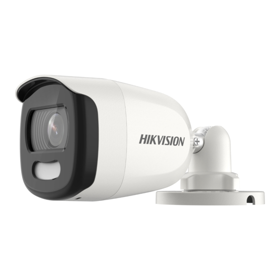
5 MP Full Time Color Camera
User Manual
Thank you for purchasing our product. If there are any
questions, or requests, do not hesitate to contact the
dealer.
This manual applies to the models below:
Type I Camera
Type II Camera
Type III Camera
This manual may contain several technical mistakes or
printing errors, and the content is subject to change
without notice. The updates will be added to the new
version of this manual. We will readily improve or
update the products or procedures described in the
manual.
Type
User Manual
Model
DS-2CE10HFT-F
DS-2CE10HFT-F28
DS-2CE12HFT-F
DS-2CE12HFT-F28
DS-2CE72HFT-F
DS-2CE72HFT-F28
0100001090708
Advertisement
Table of Contents

Related Manuals for HIKVISION DS-2CE10HFT-F28


Summary of Contents for HIKVISION DS-2CE10HFT-F28
- Page 1 This manual applies to the models below: Type Model DS-2CE10HFT-F Type I Camera DS-2CE10HFT-F28 DS-2CE12HFT-F Type II Camera DS-2CE12HFT-F28 DS-2CE72HFT-F Type III Camera DS-2CE72HFT-F28 This manual may contain several technical mistakes or printing errors, and the content is subject to change without notice.
-
Page 2: Regulatory Information
Regulatory Information FCC Information Please take attention that changes or modification not expressly approved by the party responsible for compliance could void the user’s authority to operate the equipment. FCC compliance: This equipment has been tested and found to comply with the limits for a Class A digital device, pursuant to part 15 of the FCC Rules. - Page 3 Safety Instruction These instructions are intended to ensure that user can use the product correctly to avoid danger or property loss. The precaution measure is divided into “Warnings” and “Cautions”. Warnings: Serious injury or death may occur if any of the warnings are neglected.
-
Page 4: Product Features
Keep the camera away from liquid while in use for non-water-proof device. While in delivery, the camera shall be packed in its original packing, or packing of the same texture. Mark Description Table 0-1 Mark Description Mark Description DC Voltage 1 Introduction 1.1 Product Features... - Page 5 1.2.3 Overview of Type III Camera Enclosure Main Body Switch Button Power Cord DC12V Video Cable Mounting Base Figure 1-3 Overview of Type III Camera Note: Press and hold the switch button for 5 seconds to switch the video output. Four kinds of video outputs are available: TVI, AHD, CVI, and CVBS.
-
Page 6: Installation
2 Installation Before you start Make sure that the device in the package is in good condition and all the assembly parts are included. Make sure that all the related equipment is power-off during the installation. Check the specification of the products for the ... - Page 7 Note: The supplied screw package contains self-tapping screws, and expansion bolts. For cement wall/ceiling, expansion bolts are required to fix the camera. For wooden wall/ceiling, self-tapping screws are required. 5. Connect the corresponding power cord, and video cable. 6.
- Page 8 Figure 2-6 Secure the Junction Box on the Wall/Ceiling 6. Route the cables through the bottom cable hole, or the side cable hole of the junction box. 7. Combine the junction box cover with its body. Figure 2-7 Combine the Junction Box Cover back to its Body 8.
- Page 9 Note: Drill the cable hole, when adopting the ceiling outlet to route the cable. 3. Route the cables through the cable hole, or the side opening. 4. Attach the bracket to the ceiling, and secure the camera with supplied screws. Figure 2-9 Secure the Camera to the Ceiling Note: The supplied screw package contains self-tapping...
- Page 10 3. Paste the drill template (supplied) to the place where you want to install the camera. 4. Drill the screw holes and the cable hole (optional) according to the drill template. Figure 2-13 Drill Template Note: Drill the cable hole, when adopting the ceiling outlet to route the cable.
-
Page 11: Ceiling/Wall Mounting With Junction Box
2). Move the camera body up and down to adjust the tilt position [0° to 75°]. 3). Rotate the main body to adjust the rotation position [0° to 360°]. Ceiling/Wall Mounting with Junction Box 2.3.2 Before you start: You need to purchase a junction box in advance. The installation of ceiling mounting and wall mounting are similar. - Page 12 8. Repeat the step 7 to 9 of 2.3.1 Ceiling/Wall Mounting without Junction Box to finish the installation. Figure 2-20 Finish the Installation...
-
Page 13: Menu Description
3 Menu Description Please follow the steps below to call the menu. Note: The actual display may vary with your camera model. Steps: 1. Connect the camera with the TVI DVR, and the monitor, shown as the figure 3-1. Figure 3-1 Connection 2. -
Page 14: Video Format
1). Click up/down direction button to select the item. 2). Click Iris + to confirm the selection. 3). Click left/right direction button to adjust the value of the selected item. 3.1 VIDEO FORMAT You can set the video format to 5MP@20fps, 4MP@30fps, 4MP@25fps, 2MP@30fps or 2MP@25fps. -
Page 15: Image Mode
VIDEO SETTINGS IMAGE MODE WHITE BALANCE BRIGHTNESS CONTRAST SHARPNESS SATURATION 3DNR MIRROR BACK EXIT SAVE & EXIT Figure 3-3 VIDEO SETTING IMAGE MODE IMAGE MODE is used to adjust the image saturation, and you can set it to STD (Standard) or HIGH-SAT (High Saturation). -
Page 16: Factory Default
between two frames besides processing the noise in one frame. The noise will be much less and the video will be clearer. MIRROR OFF, H, V, and HV are selectable for mirror. OFF: The mirror function is disabled. H: The image flips 180° horizontally. V: The image flips 180°...
Need help?
Do you have a question about the DS-2CE10HFT-F28 and is the answer not in the manual?
Questions and answers