Table of Contents
Advertisement
Quick Links
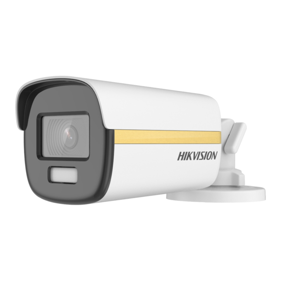
4K ColorVu PoC Camera
User Manual
Thank you for purchasing our product. If there are any
questions, or requests, do not hesitate to contact the
dealer.
This manual applies to the models below:
Type I Camera
Type II Camera
Type III Camera
This manual may contain several technical mistakes or
printing errors, and the content is subject to change
without notice. The updates will be added to the new
version of this manual. We will readily improve or update
the products or procedures described in the manual.
Type
User Manual
Model
DS-2CE12UF3T-E
DS-2CE10UF3T-E
DS-2CE72UF3T-E
02010020200721
Advertisement
Table of Contents

Related Manuals for HIKVISION DS-2CE12UF3T-E


Summary of Contents for HIKVISION DS-2CE12UF3T-E
- Page 1 This manual applies to the models below: Type Model Type I Camera DS-2CE12UF3T-E Type II Camera DS-2CE10UF3T-E Type III Camera DS-2CE72UF3T-E This manual may contain several technical mistakes or printing errors, and the content is subject to change without notice.
- Page 2 SATISFACTORY QUALITY, OR FITNESS FOR A PARTICULAR PURPOSE. THE USE OF THE PRODUCT BY YOU IS AT YOUR OWN RISK. IN NO EVENT WILL HIKVISION BE LIABLE TO YOU FOR ANY SPECIAL, CONSEQUENTIAL, INCIDENTAL, OR INDIRECT DAMAGES, INCLUDING, AMONG OTHERS,...
- Page 3 IN THE EVENT OF ANY CONFLICTS BETWEEN THIS MANUAL AND THE APPLICABLE LAW, THE LATER PREVAILS. Regulatory Information FCC Information Please take attention that changes or modification not expressly approved by the party responsible for compliance could void the user’s authority to operate the equipment.
- Page 4 Safety Instruction These instructions are intended to ensure that user can use the product correctly to avoid danger or property loss. The precaution measure is divided into “Warnings” and “Cautions”. Warnings: Serious injury or death may occur if any of the warnings are neglected.
- Page 5 Keep the camera away from liquid while in use for non-water-proof device. While in delivery, the camera shall be packed in its original packing, or packing of the same texture.
-
Page 6: Table Of Contents
TABLE OF CONTENTS 1 Introduction ..............1 1.1 Product Features ..............1 1.2 Overview ................1 1.2.1 Overview of Type I Camera ........1 1.2.2 Overview of Type II Camera ........1 1.2.3 Overview of Type III Camera ........1 2 Installation.............. -
Page 7: Introduction
1 Introduction 1.1 Product Features The main features are as follows: High performance CMOS sensor OSD menu with configurable parameters 24-hour color image Smart light 3-axis adjustment Power over coaxial 1.2 Overview 1.2.1 Overview of Type I Camera Power Cord Bracket Video Cable... -
Page 8: Installation Of Type I Camera
disassemble the camera for repair or maintenance by yourself. Installation of Type I Camera 2.1.1 Ceiling/Wall Mounting Without Junction Box Before you start: Ceiling mounting and wall mounting are similar. Following steps take ceiling mounting as an example. Steps: 1. Paste the drill template (supplied) to the place where you want to install the camera. - Page 9 You need to purchase a junction box in advance. Ceiling mounting and wall mounting are similar. Following steps take wall mounting as an example. Steps: 1. Paste the drill template for junction box to the place where you want to install the camera. 2.
-
Page 10: Installation Of Type Ii Camera
9. Repeat steps 6 to 7 of 2.2.1 Ceiling/Wall Mounting Without Junction Box to finish the installation. Installation of Type II Camera 2.2.1 Ceiling/Wall Mounting Without Junction Box Before you start: Ceiling mounting and wall mounting are similar. Following steps take ceiling mounting as an example. Note: For installation with junction box, refer to 2.1.2 Ceiling/Wall Mounting with Junction Box. -
Page 11: Installation Of Type Iii Camera
Installation of Type III Camera 2.3.1 Ceiling Mounting without Junction Box Steps: 1. Paste the drill template (supplied) to the place where you want to install the camera. 2. (Optional) For cement ceiling, drill the screw holes with a 5.5 mm drill and insert the supplied wall plugs. -
Page 12: Ceiling Mounting With Junction Box/Inclined Ceiling Mount
2). Move the main body up and down to adjust the tilt position [0° to 75°]. 3). Rotate the main body to adjust the rotation position [0° to 360°]. 2.3.2 Ceiling Mounting with Junction Box/Inclined Ceiling Mount Before you start: You need to purchase a junction box or inclined ... -
Page 13: Wall Mounting
Figure 2-19 Snap Camera into Gang Box 8. Secure the junction box body on the ceiling with four PA4 × 25 screws. Figure 2-20 Secure Junction Box Body 9. Route the cables through the bottom cable hole or the side cable hole of the junction box and connect the cables. -
Page 14: Menu Description
Figure 2-23 Fix Gang Box 4. Repeat the step 4 to 7 of 2.3.1 Ceiling Mounting without Junction Box to finish the installation. Figure 2-24 Finish Installation 3 Menu Description Please follow the steps below to call the menu. Note: The actual display may vary with your camera model. - Page 15 VIDEO FORMAT EXPOSURE MODE EXPOSURE ANTI- BANDING BACK EXIT SAVE & EXIT IMAGE MODE WHITE BALANCE BRIGHTNESS CONTRAST VIDEO SHARPNESS SETTINGS SATURATION 3 DNR MIRROR BACK EXIT SAVE & EXIT MAIN MENU LIGHT SMART THRESHOLD LIGHT LEVEL BACK EXIT SAVE & EXIT MOTION DET PRIVACY FUNCTIONS...
-
Page 16: Video Format
3.1 VIDEO FORMAT You can set the video format to 8MP@12.5fps, 8MP@15fps, 5MP@20fps, 1080p@25fps, or 1080p@30fps. 3.2 EXPOSURE EXPOSURE MODE You can set the EXPOSURE MODE to GLOBAL, BLC, HLC, WDR, or HLS. GLOBAL GLOBAL refers to the normal exposure mode that adjusts lighting distribution, variations, and non-standard processing. - Page 17 VIDEO SETTINGS IMAGE MODE WHITE BALANCE BRIGHTNESS CONTRAST SHARPNESS SATURATION 3DNR MIRROR BACK EXIT SAVE & EXIT Figure 3-3 VIDEO SETTINGS IMAGE MODE IMAGE MODE is used to adjust the image saturation, and you can set it to STD (Standard), HIGH-SAT (High Saturation), or HIGHLIGHT (better indoor facial details).
-
Page 18: Smart Light
digital noise reduction function processes the noise between two frames besides processing the noise in one frame. The noise will be much less and the video will be clearer. MIRROR OFF, H, V, and HV are selectable for mirror. OFF: The mirror function is disabled. H: The image flips 180°...
Need help?
Do you have a question about the DS-2CE12UF3T-E and is the answer not in the manual?
Questions and answers