Sign In
Upload
Download
Table of Contents
Contents
Add to my manuals
Delete from my manuals
Share
URL of this page:
HTML Link:
Bookmark this page
Add
Manual will be automatically added to "My Manuals"
Print this page
×
Bookmark added
×
Added to my manuals
Manuals
Brands
Amazone Manuals
Farm Equipment
ED 302
Operator's manual
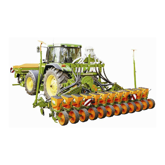
Amazone ED 302 Operator's Manual
Precision airplanter
Hide thumbs
Also See for ED 302
:
Operating manual
(196 pages)
1
2
3
4
Table Of Contents
5
6
7
8
9
10
11
12
13
14
15
16
17
18
19
20
21
22
23
24
25
26
27
28
29
30
31
32
33
34
35
36
37
38
39
40
41
42
43
44
45
46
47
48
49
50
51
52
53
54
55
56
57
58
59
60
61
62
63
64
65
66
67
68
69
70
71
72
73
74
75
76
77
78
79
80
81
82
83
84
85
86
87
88
89
90
91
92
93
94
95
96
97
98
99
100
101
102
103
104
105
106
107
108
109
110
111
112
113
114
115
116
117
118
119
120
121
122
123
124
125
126
127
128
129
130
131
132
133
134
135
136
137
138
139
140
141
142
143
144
145
146
147
148
149
150
151
152
153
154
155
156
157
158
159
160
161
162
163
164
165
166
167
168
169
170
171
172
page
of
172
Go
/
172
Contents
Table of Contents
Bookmarks
Table of Contents
Table of Contents
1 User Advice
Purpose of the Document
Information about Directions in this Instruction Manual
Illustrations Used
2 General Safety Advice
Obligations and Liability
Illustration of Safety Advice
Organising Measures
Safety Device and Guards
Informal Safety Measures
Training of the Staff
Safety Measures and Normal Operation
Danger from Residual Power
Maintenance and Repair, Remedy of Faults
Constructional Changes
Spare Parts and Wearing Parts and Auxiliary Parts
Cleaning and Disposal
Workplace of the Operator
Safety Symbols and Other Identifications on the Machine
Positioning of Warning Decals and Other Identifications
Danger When Not Adhering to the Safety Advice
Conscious Operation
Safety Advice for the Operator
General Safety and Accident Prevention Advice
Hydraulic System
Electric Outfit
Maintenance, Repair- and Care-Work
Mounted Implements
Operation with PTO Shafts
Seed Drill Operation
3 Loading
Loading of ED 302 and ED 452 Precision Airplanters
Loading the ED 452-K and ED 602-K Precision Airplanter
Loading the ED 902-K Precision Airplanter
4 Description of Product
Overview - Components
Overview - Supply Lines between Tractor and Machine
Traffic Safety Device (Optional Equipment)
Designed Use
Danger Zones
Conformity
Type Plate and CE Declaration
Technical Data
Required Tractor Equipment
Details about Noise Level
5 Assembly and Function
Classic Seeder Unit
Contour Seeder Unit
Seed Metering
Adjustable Row Spacings
Grain Spacing
Grain Spacing (Tabular)
Grain Spacing (by Way of Calculation)
Determination of Chain Wheel Pairings for Setting- and Secondary Gearboxes
Track Markers
Wheel Mark Eradicators (Option)
Under Root Fertilising (Option)
Fertiliser Coulters
Electronic Monitoring and Operation (Option)
6 Putting into Operation
First Operation
Determining the Actual Values for the Tractor Total Weight, Tractor Axle Loads, Tyre Carrying Capacity as Well as the Required Minimum Ballast Weights
Required Data for the Calculation
Calculation of the Minimum Ballast Front G V Min to Ensure the Steer Ability
Calculation of the Actual Front Axle Load T
Calculation of the Actual Total Weight of the Combination Tractor/Mounted Implement
Tat
Calculation of the Actual Rear Axle Load T
Tyre Carrying Capacity
H Tat
Table
Table
Matching up the PTO Shaft to the Tractor
Fitting Advice for the Connection of the Hydraulic Impeller Drive (Option)
Fitting Instruction Profi Control (Option)
Initial Fitting of the Operator Terminal (Option)
Initial Fitting of the Clod Clearer (Option, Contour Seeder Unit)
Initial Fitting of the Parking Device ED902-K (Option)
7 Coupling and Uncoupling the Machine
Coupling the Machine
Hydraulic Connections
One Control Valve for Two Machine Functions (Switching Unit, Option)
Hydraulic Connection Profi Control
Establishing the Power Supply Connections
Connection of Pressure Gauge
Support Stands (All Types, Except Folded ED 902-K)
Uncoupling the Machine
Parking the Folded ED 902-K on the Parking Support Stand
8 Settings
Setting the Row Spacing
Switching off the Seeder Units
Switching off the Seeder Units Mechanically
Switching off the Seeder Units Electronically (Option)
Setting the Grain Spacing in the Setting Gearbox
Setting the Grain Spacing in the Secondary Gearbox
Matching the Seeder Units to the Seed
Exchange of Singling Disc and Ejector, Setting the Strippers and Reduction Flap
Checking the Stripper Position and Reduction Flap Position
Filling and Emptying the Seed Hopper
Filling the Seed Hopper
Emptying the Seed Hopper and Seed Housing
Sowing Coulter Tips
Impeller Rev. Speed
Universal Joint Shaft Impeller Drive
Hydraulic Impeller Drive
Setting the Impeller Rev. Speed on the Current Regulating Valve of the Tractor
Setting the Impeller Rev. Speed on the Current Regulating Valve of the Machine
Setting the Impeller Rev. Speed on the Front Tank
Setting the Track Markers
Calculation of Track Marker Arm Length to Trace a Track in the Tractor's Centre
Calculation of the Track Marker Arm Length to Trace a Track in the Tractor Wheel Mark
Setting the Work Intensity of the Track Marker
Setting the Track Markers (ED 302)
Setting the Track Markers (ED 452 [-K])
Setting the Track Markers (ED 602-K)
Setting the Track Markers (ED 902-K)
Fitting the Short Marker Arm Ends
Setting the Wheel Mark Eradicators
Setting the Seed Placement Depth (Classic Seeder Unit)
Setting the Load Stage (Classic Seeder Unit)
Setting the Seed Placement Depth (Contour Seeder Unit)
Setting the Load Stage (Contour Seeder Unit)
Changing the Press Roller Load Distribution (Contour Seeder Unit)
Setting the Clod Clearers (Contour Seeder Unit)
Checking the Seed Placement Depth and the Grain Spacing
Closing the Seed Furrow (Classic Seeder Unit)
Closing the Seed Furrow (Contour Seeder Unit)
Setting the Intermediate Press Roller (Contour Seeder Unit)
Setting the Fertiliser Coulters
Fertiliser Hopper (2 X 220 L)
Filling the Fertiliser Hopper (2 X 220 L)
Setting the Fertiliser Rate
8.17.2.1 Setting the Drive Gear Ratio
8.17.2.2 Setting the Metering Setting Rings
Residue Emptying of Fertiliser Hopper (2 X 220 L)
Fertiliser Hopper (900 L and 1100 L)
Filling the Fertiliser Hopper (900 L and 1100 L)
Setting the Fertiliser Rate
8.18.2.1 Determination of Gearbox Setting Figure
Emptying the Fertiliser Hopper
Calibration Test (2X220L-Hopper and 900L/1100L-Hopper)
Front Tank
Setting the Fertiliser Rate
Calibration Test
Fertiliser Filling Worm Auger (Option)
9 Transport on Public Roads
10 Operation
Starting the Operation
Transport Securing Device of the Track Markers (ED 302 and ED 452 [-K])
Folding the Machine Wings
Folding Machine Wings and Track Markers (ED 452-K and ED 602-K)
Folding the Machine Wings and Track Markers (ED 902-K)
Track Marker Actuation
Turning at the Headlands
11 Faults
Standstill of a Singling Disc
Shearing off of a Track Marker Arm
12 Maintenance, Repair and Care
Cleaning
Cleaning the Machine
Cleaning the Vacuum Impeller
Cleaning the Filling Worm Auger
Lubrication Advice
Overview Lubrication Points
Maintenance and Care - Review
Wheel Bolt Torques
Tyre Pressure
Checking the Oil Level in the Setting Gearbox (900/1000 L Fertiliser Hopper)
Hydraulic System
Mounting and Dismounting Hydraulic Hoses
Checking the V-Belt in the Impeller Belt Drive (Authorised Workshop)
Roller Chains and Chain Wheels
Checking the Seeder Units
Checking / Exchanging Sowing Coulter Tips
Checking / Exchanging the Drag Fertiliser Coulter Tips
Bolt Torques
Advertisement
Quick Links
Download this manual
Operator's manual
az
ED 302
ED 452
ED 452-K
ED 602-K
ED 902-K
Precision Airplanter
Before starting operation,
MG 1239
please carefully read and
BAH0002 10.05
adhere to this operator's
Printed in Germany
manual and safety advice!
1
ED BAH0002 10.05
Table of
Contents
Previous
Page
Next
Page
1
2
3
4
5
Advertisement
Table of Contents
Need help?
Do you have a question about the ED 302 and is the answer not in the manual?
Ask a question
Questions and answers
Related Manuals for Amazone ED 302
Farm Equipment Amazone ED 302 Operating Manual
Precision airplanter (196 pages)
Farm Equipment Amazone EDX 9000-TC Operating Manual
(246 pages)
Farm Equipment Amazone EDX 9000-TC Service Manual
Precision air planter xpress singling / electronics / hydraulics (140 pages)
Farm Equipment Amazone EDX 6000 TC Operating Manual
Precision airplanter (234 pages)
Farm Equipment Amazone EasyCheck Original Operating Manual
(14 pages)
Farm Equipment Amazone EDX 6000-2 Operating Manual
Precision airplanter (155 pages)
Farm Equipment Amazone EDX 6000-2C Service Manual
Precision air planter xpress singling / electronics / hydraulics (140 pages)
Farm Equipment Amazone ED 902-K Operator's Manual
Precision airplanter (172 pages)
Farm Equipment Amazone UX 6201 Super Operating Manual
Trailed field sprayer with comfort package cp plus (250 pages)
Farm Equipment Amazone Groundkeeper Jumbo SMARTCUT Operating Manual
(64 pages)
Farm Equipment Amazone Centaya 3000 Super 1600 Operating Manual
Pneumatic pack top seed drill (230 pages)
Farm Equipment Amazone Cayron 200 Operating Manual
Reversible plough (82 pages)
Farm Equipment Amazone AMATRON+ Instruction Manual
Mobile fertiliser test kit (52 pages)
Farm Equipment Amazone ZG-TS 7501 Truck Operating Manual
Pack top spreader (94 pages)
Farm Equipment Amazone XTender 2200 Operating Manual
Rear-mounted hopper (108 pages)
Farm Equipment Amazone AD-P 303 Special Operating Manual
Top mounted seed drills (192 pages)
This manual is also suitable for:
Ed 452
Ed 452-k
Ed 602-k
Ed 902-k
Table of Contents
Print
Rename the bookmark
Delete bookmark?
Delete from my manuals?
Login
Sign In
OR
Sign in with Facebook
Sign in with Google
Upload manual
Upload from disk
Upload from URL


Need help?
Do you have a question about the ED 302 and is the answer not in the manual?
Questions and answers