
Related Manuals for Amazone EDX 6000 TC


Summary of Contents for Amazone EDX 6000 TC
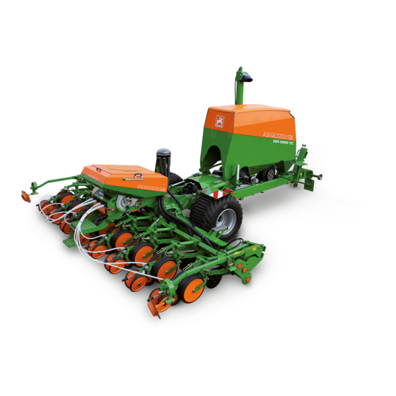
- Page 1 Operating Manual Precision airplanter EDX 6000-TC Please read this operating manual before initial operation. MG3983 Keep it in a safe place for BAH0047-7 09.19 future use!
- Page 2 Reading the instruction manual and to adhere to it should not appear to be inconvenient and superfluous as it is not enough to hear from others and to realise that a machine is good, to buy it and to believe that now everything would work by itself.
- Page 3 + 49 (0) 5405 501-234 E-mail: amazone@amazone.de Spare part orders Spare parts lists are freely accessible in the spare parts portal at www.amazone.de. Please send orders to your AMAZONE dealer. Formalities of the operating manual Document number: MG3983 Compilation date: 09.19 ...
- Page 4 Send us your suggestions by fax. AMAZONEN-WERKE H. DREYER GmbH & Co. KG Postfach 51 D-49202 Hasbergen, Germany Tel.: + 49 (0) 5405 50 1-0 Fax: + 49 (0) 5405 501-234 E-mail: amazone@amazone.de EDX 6000-TC BAH0047-7 09.19...
-
Page 5: Table Of Contents
Table of Contents User information ..................10 Purpose of the document ....................... 10 Location information in the operating manual ................ 10 Presentations used ........................ 10 General Safety Instructions ..............11 Obligations and liability ...................... - Page 6 Table of Contents 4.12 Noise production data ......................58 Structure and function ................59 Radar ............................. 61 Service brake system ......................62 5.2.1 Safety chain for implements without brake system (optional) ..........62 ...
- Page 7 Table of Contents 6.1.1.5 Calculation of the actual rear axle load of the tractor T ............ 97 H tat 6.1.1.6 Tyre load capacity ........................97 6.1.1.7 Table ............................98 6.1.2 Requirements for tractor operation with attached implements ..........99 ...
- Page 8 Table of Contents Transportation ..................153 Set the implement to road transport mode ................156 Legal regulations ......................... 159 Use of the implement ................160 10.1 Folding/unfolding the implement sections and track markers ..........162 ...
- Page 9 Table of Contents 12.6.14 Hydraulic system (specialist workshop) ................215 12.6.14.1 Labelling of hydraulic hose lines ..................216 12.6.14.2 Maintenance intervals ......................216 12.6.14.3 Inspection criteria for hydraulic hose lines ................217 12.6.14.4 Installation and removal of hydraulic hose lines ..............
-
Page 10: User Information
User information User information The User information section provides information concerning the operating manual. Purpose of the document This operating manual describes the operation and maintenance of the implement provides important information on safe and efficient handling of the implement ... -
Page 11: General Safety Instructions
General Safety Instructions General Safety Instructions This section contains important information on safe operation of the implement. Obligations and liability Comply with the instructions in the operating manual Knowledge of the basic safety information and safety regulations is a basic requirement for safe handling and fault-free implement operation. - Page 12 General Safety Instructions Risks in handling the implement The implement has been constructed to the state-of-the art and the recognised rules of safety. However, operating the implement may cause risks and restrictions the health and safety of the user or third persons ...
-
Page 13: Presentation Of Safety Symbols
General Safety Instructions Presentation of safety symbols Safety instructions are indicated by the triangular safety symbol and the highlighted signal word. The signal word (DANGER, WARNING, CAUTION) describes the severity of the risk, and carries the following meaning: DANGER Indicates an immediate hazard with high risk, which will result in death or serious bodily harm (loss of limbs or long-term harm), if it is not avoided. -
Page 14: Organisational Measures
General Safety Instructions Organisational measures The operator must provide the necessary personal protective equipment as per the information provided by the manufacturer of the crop protection agent to be used, such as: Safety glasses Protective shoes Chemical-resistant overalls ... -
Page 15: User Training
General Safety Instructions User training Only those people who have been trained and instructed may work with/on the implement. The operator must clearly specify the responsibilities of the people charged with operation and maintenance work. People being trained may only work with/on the implement under the supervision of an experienced person. -
Page 16: Safety Measures In Normal Operation
General Safety Instructions Safety measures in normal operation Only operate the implement if all the safety and protection equipment is fully functional. Check the implement at least once a day for visible damage and check the function of the safety and protection equipment. Danger from residual energy Note that there may be residual mechanical, hydraulic, pneumatic and electrical/electronic energy on the implement. -
Page 17: Spare And Wear Parts And Aids
Immediately replace any implement parts which are not in a perfect state. Use only genuine AMAZONE spare and wear parts or the parts cleared by AMAZONEN-WERKE so that the operating permit retains its validity in accordance with national and international regulations. If... -
Page 18: Warning Symbols And Other Markings On The Machine
General Safety Instructions 2.13 Warning symbols and other markings on the machine Always keep all the warning symbols of the implement clean and in a legible state. Replace illegible warning symbols. You can obtain the warning symbols from your dealer using the order number (e.g. MD 075). - Page 19 General Safety Instructions Order number and explanation Warning signs MD 078 Risk of crushing of fingers/hand by accessible, moving parts of the implement! This hazard can cause the most severe injuries with loss of body parts. Never reach into the hazardous area while the engine of the tractor with connected universal joint shaft/hydraulic system/electronic system is running.
- Page 20 General Safety Instructions MD 083 Danger of arms being drawn in and/or caught by moving parts involved in the working process! This hazard can cause the most severe injuries with loss of body parts. Never open or remove protective devices while the tractor engine is running with the universal joint shaft/hydraulic or electronic systems connected.
- Page 21 General Safety Instructions MD 095 Before commissioning the implement read and observe the operating manual and the safety instructions carefully! MD 096 Danger from escaping high-pressure hydraulic fluid due to leaking hydraulic hose lines. This danger may cause serious injuries, perhaps even resulting in death, if escaping high-pressure hydraulic fluid passes through the skin and into the body.
- Page 22 General Safety Instructions MD 101 This symbol indicates jacking points for lifting gear (jack). MD 102 Danger from intervention in the implement, e.g. installation, adjusting, troubleshooting, cleaning, maintaining and repairing, due to the tractor and the implement being started unintentionally and rolling. These dangers can cause extremely serious and potentially fatal injuries.
- Page 23 General Safety Instructions MD 110 This pictogram identifies parts of the implement that serve as a handle. MD 119 Nominal speed (maximum 1000 rpm) and direction of rotation of the drive shaft on the implement side. MD 174 Danger from unintended continued movement of the implement.
- Page 24 General Safety Instructions MD 181 Check that the wheel nuts are secure. after the first 10 operating hours after a wheel change. MD 187 Risk of injury to unprotected body parts! Seed grains may emerge uncontrollably at high speeds and cause injuries particularly to the eyes.
-
Page 25: Position Of The Warning Signs And Other Markings
General Safety Instructions 2.13.1 Position of the warning signs and other markings Warning signs The following diagrams show the arrangement of the warning symbols on the implement. Fig. 1 Fig. 2 EDX 6000-TC BAH0047-7 09.19... - Page 26 General Safety Instructions Fig. 3 Fig. 4 Fig. 6 Fig. 5 EDX 6000-TC BAH0047-7 09.19...
-
Page 27: Dangers In Case Of Non-Observance Of The Safety Instructions
General Safety Instructions 2.14 Dangers in case of non-observance of the safety instructions Non-compliance with the safety instructions can pose both a danger to people and to the environment and implement Can lead to the loss of all warranty claims. In particular, non-compliance with the safety information could pose the following risks: ... - Page 28 General Safety Instructions immediate area of the implement (children). Ensure that you can see clearly. It is forbidden to ride on the implement or use it as a means of transport! Drive in such a way that you always have full control over the tractor with the attached implement.
- Page 29 General Safety Instructions tensioning, kinking or rubbing must not chafe against other parts. The release ropes for quick action couplings must hang loosely and may not release themselves when lowered. Also ensure that uncoupled implements are stable! Use of the implement ...
- Page 30 General Safety Instructions Implement transportation When using public roads, national road traffic regulations must be observed. Switch off the on board computer before road transport Before moving off, check: the correct connection of the supply lines, ...
-
Page 31: Attached Implements
General Safety Instructions braking (lock the pedals). Observe the maximum permissible total weight. Only transport the implement with empty seed and fertiliser hopper. 2.17 Attached implements Comply with the approved combination options for the attachment equipment on the tractor and the implement drawbar. Only couple approved combinations of vehicles (tractor and attached implement). -
Page 32: Hydraulic System
Replace the hydraulic hose lines if they are damaged or worn. Only use original AMAZONE hydraulic hose lines. The hydraulic hose lines should not be used for longer than six years, including any storage time of maximum two years. Even... -
Page 33: Electrical System
General Safety Instructions 2.17.2 Electrical system When working on the electrical system, always disconnect the battery (negative terminal). Only use the prescribed fuses. If fuses are used that are too highly rated, the electrical system will be destroyed – risk of fire. ... -
Page 34: Brake System
General Safety Instructions 2.17.3 Brake system Only specialist workshops or recognised brake services can carry out adjustment and repair work on the brake system. Have the brake system thoroughly checked regularly. If there are any functional faults in the brake system, stop the tractor immediately. -
Page 35: Tyre
General Safety Instructions Hydraulic brake system for export implements Hydraulic brake systems are not approved in Germany. When filling up or replacing the brake fluid, use the prescribed hydraulic fluids. When replacing the hydraulic fluids, comply with the appropriate regulations. 2.17.4 Tyre ... -
Page 36: Operation Of The Precision Airplanter
Spare parts must meet at least the specified technical requirements of AMAZONEN-WERKE! This is ensured through the use of original AMAZONE spare parts. EDX 6000-TC BAH0047-7 09.19... -
Page 37: Loading And Unloading
Loading and unloading Loading and unloading Important information The implement sections may only be folded if: all hydraulic supply lines on the tractor are connected; the AMATRON 3 on-board computer is connected. To avoid damaging the implement, fold the implement sections as described in "Fig. -
Page 38: Removal Of Individual Implement Components In Order To Comply With The Permitted Transport Height
Loading and unloading Removal of individual implement components in order to comply with the permitted transport height The following work must be carried out in order to comply with the permitted transport height of the implement and transport vehicle: 1. Label and remove the seed tubes (Fig. 9/1). Fig. -
Page 39: Fastening The Seed Tube Hoses
Loading and unloading 3.2.1 Fastening the seed tube hoses Remove the union nut (Fig. 12/1) completely from the opto-sensor (Fig. 12/3), and pull the seed tube along with the cutting ring (Fig. 12/2) out of the opto-sensor. Fig. 12 Always insert the seed tube as far as it will go to prevent seed accumulating in front of the seed tube. -
Page 40: Loading And Unloading With A Tractor
Loading and unloading Loading and unloading with a tractor DANGER The implement can also be equipped without its own brake system. There is a risk of accident if the tractor is unsuitable. if the brake system of the implement is not connected to the tractor and filled. -
Page 41: Loading The Attached Implement
Loading and unloading 3.3.1 Loading the attached implement 1. Attach the implement to a suitable tractor for loading onto a transport vehicle, see "Start-up", Seite 93; "Coupling and uncoupling the implement", Seite 102. 2. Remove individual implement components in order to comply with the permitted transport height (see 3.2, Seite 38). -
Page 42: Unloading The Attached Implement
Loading and unloading 3.3.2 Unloading the attached implement 1. Attach the implement to a suitable tractor for unloading from the transport vehicle, see "Start-up", Seite 93; "Coupling and uncoupling the implement", Seite 102. 2. Remove the transport securing device. 3. -
Page 43: Product Description
Product description Product description This section: provides a comprehensive overview of the implement's structure. provides the names of the individual assembly groups and operating controls. If possible, read this section when actually at the implement. This helps you to understand the implement better. Overview of assembly groups Fig. - Page 44 Product description Fig. 20/… (1) Case for stowing of the operating manual the metering roller of the digital scale Fig. 20 Fig. 21/… (1) Tensioned crosspiece (2) Drawbar, extendable (3) Jack, foldable (4) Step Fig. 21 Fig. 22/… Mount for supply lines Fig.
- Page 45 Product description Fig. 24/… (1) Fill level sensor (seed) (2) Sensor (compressed air) Fig. 24 Fig. 24/... (1) Setting lever for the seed shutter Fig. 25 Fig. 24/... (1) Setting lever for the air deflector Fig. 26 Fig. 27/... (1) Setting lever for the sealing lip Fig.
- Page 46 Product description Fig. 24/... (1) Setting lever for the mech. adjustable seed scraper Fig. 28 Fig. 24/... (1) Indicator for the electrically adjustable seed scraper Fig. 29 Fig. 30/… Double disc coulter Fig. 30 Fig. 31/… (1) Roller tarpaulin (fertiliser hopper) Fig.
- Page 47 Product description Fig. 32/… (1) Fill level sensor (fertiliser) Fig. 32 Fig. 33/… (1) Fertiliser metering unit (2) Injector sluice (3) Electric motor (fertiliser roller drive) Fig. 33 Fig. 34/… (1) Calibration trough (fertiliser) in mounting for calibration test Fig. 34 Fig.
-
Page 48: Electronic Monitoring And Operation (Optional)
Product description Electronic monitoring and operation (optional) The precision airplanter is electronically monitored and controlled using a control terminal. Observe the corresponding operating manual when using the implement with the control terminal! AMATRON 3 Fig. 36/.: monitored function ISOBUS implement control Fig. -
Page 49: Camera System (Option)
Product description Camera system (option) The camera (Fig. 39/1) at the rear of the implement makes the area hidden by the hopper visible. The large monitor in the tractor cab displays the work performed by the implement tools and the filling funnel for the filling auger. Make sure nobody is standing between the supply vehicle and filling funnel during manoeuvring. - Page 50 Product description Fig. 42/… (1) Locking of implement sections in transport position Fig. 42 Fig. 43/… Wheel chocks Fig. 43 EDX 6000-TC BAH0047-7 09.19...
-
Page 51: Overview - Supply Lines Between The Tractor And The Implement
Product description Overview – Supply lines between the tractor and the implement All hydraulic hose lines are equipped with grips. Coloured markings with a code number or code letter have been applied to the gripping sections in order to assign the respective hydraulic function to the pressure line of a tractor control unit! Films are stuck on the implement for the markings that illustrate the respective hydraulic function. -
Page 52: Transportation Equipment
Product description Description Marking Function Brake line yellow (See section 7.1, Seite Dual-circuit pneumatic braking system 103.) Supply line Description Function Implement plug (see section 5.3, Seite 64) AMATRON 3 on-board computer Connector (7-pin) Road traffic lighting system Hydraulic brake line (see section 7.2, Seite 109) Hydraulic service brake system not allowed in Germany and in many other EU countries Transportation equipment... -
Page 53: Proper Use
adherence of inspection and maintenance work Exclusive use of genuine AMAZONE spare parts. Other uses to those specified above are forbidden and shall be considered as improper. For any damage resulting from improper use ... -
Page 54: Danger Areas And Danger Points
Product description Danger areas and danger points The danger area is the area around the implement in which people can be caught: by work movements made by the implement and its tools by materials or foreign bodies thrown out of the implement ... -
Page 55: Rating Plate And Ce Mark
Product description Rating plate and CE mark The diagram shows the location of the rating plate and the CE mark. The CE mark on the implement indicates compliance with the stipulations of the valid EU directives. The rating plate specifies: ... -
Page 56: Technical Data
Product description 4.10 Technical data Precision airplanter EDX 6000-TC Number of seeding units Row spacing See table (Fig. 49) Working width Payload for the seed hopper (on the field) Volume of the fertiliser hopper 2800 Working speed [km/h] Power requirement (from) [kW/bhp] as of 125/170 Oil flow rate (minimum) -
Page 57: Necessary Tractor Equipment
Product description Road transport data (only with empty fertiliser and seed hopper!) Precision airplanter EDX 6000-TC Total width (in transport position) Total length (in transport position) Total height (in transport position, without seed tubes and step) Tare weight (basic weight) [kg] 5600 Permissible total weight... -
Page 58: Noise Production Data
Product description Hydraulic system Maximum operating pressure: 210 bar Tractor pump capacity: At least 80 l/min at 150 bar Implement hydraulic fluid: HLP68 DIN 51524 The implement hydraulic fluid is suitable for the combined hydraulic fluid circuits of all standard tractor brands. Yellow tractor control unit: Double-acting control unit Green tractor control unit:... -
Page 59: Structure And Function
Structure and function Structure and function The following section provides information on the implement structure and the functions of the individual components. Fig. 50 The EDX 6000-TC has a centrally positioned seed hopper (Fig. 50/1). The seeding spread rate is adjusted by entering the desired values using the keys on the AMATRON 3 on-board computer. - Page 60 Structure and function The fertiliser is conveyed from the injector sluice to the distributor head (Fig. 50/10) and then distributed evenly onto all fertiliser coulters (Fig. 50/11). The fertiliser is placed in the soil beside the seed. The depth adjustment of the fertiliser coulters is adjusted centrally by actuating a tractor control unit.
-
Page 61: Radar
Structure and function As an option, each seed tube (Fig. 52/1) can be closed off by a swivelling module (Fig. 52/2). The modules are controlled by the on-board computer (see AMATRON 3 operating manual). Fig. 52 By closing the seed tubes using the modules (Fig. -
Page 62: Service Brake System
Structure and function Service brake system In Germany and many other countries, the implement may only be transported on public roads when equipped with a dual-circuit pneumatic service braking system. In several other countries, the implement may only be operated with the hydraulic service brake system. -
Page 63: Parking Brake
Structure and function 5.2.3 Parking brake Implements with a dual-circuit pneumatic service brake system and hydraulic service brake system are fitted with a parking brake. The crank (Fig. 57/1) is used to activate the parking brake. Engaging the parking brake: Turn the crank to the right (R). -
Page 64: Amatron 3 Control Terminal
Structure and function AMATRON 3 control terminal The AMATRON 3 consists of the control terminal (Fig. 58), the basic equipment (cable and fastening materials) and the job computer on the implement. Fasten the control terminal in the tractor cab according to the AMATRON 3 operating manual. Fig. -
Page 65: Controlling The Implement With The Amatron 3 On-Board Computer
Structure and function Controlling the implement with the AMATRON 3 on-board computer The hydraulic functions of the implement are actuated via the electrohydraulic control block (shown without covers). First, the desired hydraulic function has to be selected on the AMATRON 3 before the hydraulic function can be executed using the corresponding control unit. -
Page 66: Frame And Implement Sections
Structure and function Frame and implement sections Fig. 60 The implement has a main frame (Fig. 60/1) with running gear and fertiliser hopper. a foldable rear frame (Fig. 60/2). that lifts the coulter before turning at the end of the field. ... -
Page 67: Seed Singling And Spreading
Structure and function Seed singling and spreading The specified values serve as reference values and can vary depending on the seed type! The seed hopper is equipped with a pressure- tight lockable cover (Fig. 61/1). The cover is actuated using a lockable lever (Fig. 61/2). The lid is opened with the assistance of two gas- pressure springs. - Page 68 Structure and function Singling drum Seed Number of rows Hole Note per singling drum [mm] 5.5 Maize starting at 230 TGW. Maize 4.5 Maize up to 250 TGW 4.0 3.0 Sunflowers 2.5 2.0 Sorghum ...
-
Page 69: Seed Shutter
Structure and function 5.6.2 Seed shutter The seed flows from the seed hopper to the fluid bed (Fig. 65/1) directly in front of the singling drum. The fluid bed may not be completely filled with seed. Otherwise, a fluidised bed cannot be created when air is supplied later on. -
Page 70: Air Baffle
Structure and function 5.6.3 Air baffle Air flowing through the fluid bed sets the seed grains in front of the singling drum in motion The air quantity is correctly metered when the seed grains move loosely at the viewing window (without jumping). -
Page 71: Seed Scraper
Structure and function 5.6.4 Seed scraper Multiple occupancy and gaps in the holes of the singling drum are detected by the opto-sensors after working speed has been reached. The AMATRON 3 issues an alarm. Mechanically or electrically adjustable seed scrapers remove excess seed grains. -
Page 72: Seed Scraper, Mechanically Adjustable
Structure and function 5.6.4.1 Seed scraper, mechanically adjustable Adjustment of the lever (Fig. 73/1) changes the scraper position. The numbers on the scale indicated by the indicator (Fig. 73/2) on the lever are provided for guidance. The setting values can be found in Table ( Fig. 72). -
Page 73: Baffle Plate (Optional), For Working On Slopes
Structure and function 5.6.5 Baffle plate (optional), for working on slopes When working on sloping terrain, the seed may shift inside the singling unit. In this case, individual holes on the drum or entire rows are no longer supplied with seed. Baffle plates (Fig. -
Page 74: Blower Fan For Seed Singling And Fertiliser Delivery
Structure and function 5.6.7 Blower fan for seed singling and fertiliser delivery The blower fan (Fig. 79/1) generates the air current for the seed singling unit, for the fertiliser delivery. The blower fan hydraulic motor (Fig. 79/2) is driven by ... -
Page 75: Connecting The Blower Fan To The Tractor Hydraulic System
Structure and function 5.6.7.1 Connecting the blower fan to the tractor hydraulic system To connect the fan hydraulic motor to the tractor hydraulic system, the tractor must be equipped with the correct hydraulic connections (see section "Installation instructions for hydraulic blower fan connection to tractor hydraulics", Seite 101). -
Page 76: Double Disc Coulter
Structure and function 5.6.8 Double disc coulter The double disc coulter (Fig. 84/1) is supported by the two carrier rollers (Fig. 84/2) and maintains a constant working depth. The diameters of the double disc coulter and carrier rollers are especially large. Remaining vegetation in front of the furrow former (Fig. -
Page 77: Coulter Pressure (Double Disc Coulter)
Structure and function 5.6.8.2 Coulter pressure (double disc coulter) The adjustable coulter pressure applies a load of up to 250 kg on the double disc coulter. The required seed placement depth is only achieved when the coulter pressure is correctly set. If the coulter pressure is too low, the necessary placement depth will not be achieved. -
Page 78: Ground Contact Pressure And Intensity Of Press Rollers
Structure and function 5.6.8.3 Ground contact pressure and intensity of press rollers The adjustable press rollers (Fig. 89/1) close the seed furrow and push soil over the seed. Fig. 89 Ground contact pressure of the press rollers The ground contact pressure of the press rollers increases with the height at which the tab (Fig. -
Page 79: Star Clearer (Optional)
Structure and function 5.6.8.4 Star clearer (optional) The star clearers (Fig. 91/1) level out the seed furrow tracks. The star clearers can be used for mulch seeding. Fig. 91 5.6.8.5 Clod clearer (optional) The clod clearers (Fig. 92/1) level out the seed furrow track. -
Page 80: Carrier Roller Scraper (Optional)
Structure and function 5.6.8.6 Carrier roller scraper (optional) Each carrier roller can be equipped with a scraper arm (Fig. 93/1). When using the scraper arm, the row spacing of the implement may not be smaller than 45 cm. The scrapers (Fig. 93/2) are adjustable. Fig. -
Page 81: Fertiliser Metering And Application
Structure and function Fertiliser metering and application 5.7.1 Fertiliser hopper The tank (Fig. 95/1) is easily accessible for filling, calibration, and emptying. The shape of the tank ensures an unobstructed view of the tools during work. The full-area opening of the hopper allows rapid filling. -
Page 82: Digital Fill Level Monitoring
Structure and function 5.7.1.1 Digital fill level monitoring A fill level sensor monitors the fertiliser level in the fertiliser hopper. When the fertiliser level reaches the fill level sensor, the AMATRON 3 displays a warning message. At the same time, an alarm signal is issued. -
Page 83: Filling Auger (Optional)
Structure and function 5.7.1.2 Filling auger (optional) The large hopper can be optionally equipped with a filling auger (Fig. 99/1). A tarpaulin prevents rain water from getting into the funnel of the filling auger. The filling auger is swivelled hydraulically into the correct position. -
Page 84: Fertiliser Metering Unit And Injector Sluice
Structure and function 5.7.2 Fertiliser metering unit and injector sluice The fertiliser is metered by a metering roller (Fig. 102/1) in the metering unit. Fig. 102 The metering roller is driven by an electric motor (Fig. 103/1). The fertiliser falls into the injector sluice (Fig. 103/2) and is conveyed to the distributor head and then the coulters by the air current. -
Page 85: Fertiliser Quantity Adjustment
Structure and function 5.7.3 Fertiliser quantity adjustment The metering roller is driven by an electric motor (Fig. 105/1). The speed of the metering roller is determined by the spread rate that is set in the AMATRON 3 and the working speed. Fig. -
Page 86: Calibration Test
Structure and function 5.7.4 Calibration test The calibration test checks whether the pre-set and actual spread rates are equivalent. Always carry out a calibration test when changing the type of fertiliser. if the same type of fertiliser is used, but with a different grain size and specific weight. -
Page 87: Single Disc Type Fertiliser Coulter
Structure and function 5.7.6 Single disc type fertiliser coulter The single disc type fertiliser coulter (Fig. 109/1) is suitable for spreading fertiliser on ploughed and mulched soil. The fertiliser placement depth is adjustable. The maximum fertiliser placement depth is 15 cm. In the tractor track, the placement depth of individual fertiliser coulters can be adjusted by turning in addition to the hydraulic adjustment. - Page 88 Structure and function The fertiliser placement depth depends on the following factors the condition of the soil the pressure acting on the central adjustment unit; the working speed. Check the placement depth at regular intervals. 5 cm is the distance set at the factory between fertiliser and seed placement.
-
Page 89: Track Marker
Structure and function Track marker The hydraulically-actuated track markers dig into the ground alternately on the left and the right of the implement. In doing so, the active track marker creates a mark. This mark serves as an reference for driving the next bout after turning at the headland. -
Page 90: Running Gear With Twin Tyres (Optional)
Structure and function Running gear with twin tyres (optional) To avoid compaction in the seedbed, a running gear with twin tyres can be used for selected row spacings. Fig. 115 5.10 Implement wheel mark eradicator (optional) The tractor wheel mark eradicators (Fig. 116/1) loosen soil compacted by the tractor tyres and produce fine earth for covering the seed furrow. -
Page 91: Lighting Of The Work Tools (Optional)
Structure and function 5.12 Lighting of the work tools (optional) The working area of the tools can be illuminated when working at night. Fig. 118/… (1) Work lights on the fertiliser hopper Fig. 118 Fig. 119/… (1) Single-row lighting on the coulter Fig. -
Page 92: Pre-Emergence Marker (Option)
Structure and function 5.13 Pre-emergence marker (option) When pre-emergence markings are being created, the track discs (Fig. 121/2) are lowered automatically and mark the tramline that has just been created. This makes the tramlines visible before the seed has germinated. The following are adjustable ... -
Page 93: Start-Up
Start-up Start-up This section contains information on initial operation of your implement on checking how you may mount/hitch the implement to your tractor. Before operating the implement for the first time the operator must have read and understood the operating manual. ... -
Page 94: Checking The Suitability Of The Tractor
Start-up Checking the suitability of the tractor WARNING Danger of breaking during operation, insufficient stability and insufficient tractor steering and braking power on improper use of the tractor! Check the suitability of your tractor before you attach or hitch the implement to the tractor. -
Page 95: Calculating The Actual Values For The Total Tractor Weight, Tractor Axle Loads And Load Capacities, As Well As The Minimum Ballast
Start-up 6.1.1 Calculating the actual values for the total tractor weight, tractor axle loads and load capacities, as well as the minimum ballast The permissible total tractor weight, specified in the vehicle documentation, must be greater than the sum of the ... -
Page 96: Data Required For The Calculation (Hitched Implement)
Start-up 6.1.1.1 Data required for the calculation (hitched implement) Fig. 124 [kg] Tractor tare weight See tractor operating manual or vehicle documentation [kg] Front axle load of the empty tractor [kg] Rear axle load of the empty tractor [kg] Front weight (if available) See front weight in technical data, or weigh [kg] Maximum drawbar load... -
Page 97: Calculation Of The Required Minimum Ballasting At The Front G
Start-up 6.1.1.2 Calculation of the required minimum ballasting at the front G of the tractor for V min assurance of the steering capability Enter the numeric value for the calculated minimum ballast G V min required on the front side of the tractor, in the table (section 6.1.1.7). -
Page 98: Table
Start-up 6.1.1.7 Table Actual value according to Approved value Double approved calculation according to tractor load capacity (two operating manual tyres) Minimum ballast front/rear Total weight Front axle load Rear axle load You can find the approved values for the total tractor weight, axle loads and load capacities in the tractor registration papers. -
Page 99: Requirements For Tractor Operation With Attached Implements
Start-up 6.1.2 Requirements for tractor operation with attached implements WARNING Risk of breakage during operation of components through unapproved combinations of connecting equipment! Ensure: that the connection device on the tractor has a sufficient permissible drawbar load for the drawbar load actually in question ... -
Page 100: Securing The Tractor/Implement Against Unintentional Start-Up And Rolling
Start-up Securing the tractor/implement against unintentional start-up and rolling WARNING Risk of crushing, shearing, cutting, being caught and/or drawn in, or impact when making interventions in the implement, through unintentional lowering of the unsecured implement when it is raised via the three-point hydraulic system of the tractor. ... -
Page 101: Installation Instructions For Hydraulic Blower Fan Connection To Tractor Hydraulics
Start-up Installation instructions for hydraulic blower fan connection to tractor hydraulics The back pressure of 10 bar must not be exceeded. The installation regulations therefore have to be complied with when connecting the hydraulic fan connection. Connect the hydraulic coupling of the pressure line (Fig. 125/5) to a single-acting or double-acting tractor control unit with priority. -
Page 102: Coupling And Uncoupling The Implement
Coupling and uncoupling the implement Coupling and uncoupling the implement When coupling and uncoupling implements, follow the instructions given in the section "Safety instructions for the operator". CAUTION Switch off the on board computer before road transport. before adjustment, maintenance and repair work. Risk of accident due to unintended movements of the metering unit or other implement components caused by radar pulses. -
Page 103: Dual-Circuit Pneumatic Service Brake System
Coupling and uncoupling the implement Dual-circuit pneumatic service brake system DANGER Before uncoupling the implement from the tractor, secure it with wheel chocks and apply the implement's parking brake. Only remove the wheel chocks once the implement has been coupled up to the tractor. Then release the implement's parking brake. - Page 104 Coupling and uncoupling the implement The dual-circuit pneumatic service brake system has: a supply line (Fig. 126/1) with coupling head (red). a brake line (Fig. 126/2) with coupling head (yellow). Fig. 126 a trailer brake valve (Fig. 127/1). Fig.
-
Page 105: Coupling The Brake And Supply Lines
Coupling and uncoupling the implement 7.1.1 Coupling the brake and supply lines WARNING Risk of contusions, cuts, dragging, catching or knocks from incorrectly functioning brake system. When coupling the brake and supply line, ensure that: the sealing rings of the coupling heads are clean. ... - Page 106 Coupling and uncoupling the implement 2. Couple the implement to the tractor. 3. Apply the tractor parking brake, switch off the tractor engine, and remove the ignition key. 4. Open the covers (1) of the coupling heads on the tractor. 5.
-
Page 107: Uncoupling The Supply And Brake Line
Coupling and uncoupling the implement 7.1.2 Uncoupling the supply and brake line DANGER Always secure the implement with the wheel chocks before you uncouple the implement from the tractor. WARNING Risk of crushing, cutting, being caught or drawn in, or impact through the accidentally rolling implement, if the service brake is released. -
Page 108: Control Elements Of The Dual-Circuit Pneumatic Service Brake System
Coupling and uncoupling the implement 2. Release the coupling head (Fig. 132) of the supply line (red). 3. Release the coupling head of the brake line (yellow). 4. Fasten the coupling heads in the empty couplings. 5. Close the covers of the coupling heads on the tractor. -
Page 109: Hydraulic Service Brake System
Coupling and uncoupling the implement Hydraulic service brake system The hydraulic service braking system acts on two braking cylinders which actuate the brake shoes in the brake drums. The tractor also has to be equipped with a hydraulic service brake system. -
Page 110: Coupling The Hydraulic Service Brake System
Coupling and uncoupling the implement 7.2.1 Coupling the hydraulic service brake system Avoid oil contamination due to soiled hydraulic couplings. DANGER Check the routing of the brake line. The brake line must not chafe on other parts. 1. Check if the implement is secured with two wheel chocks and the implement parking brake is applied. - Page 111 Coupling and uncoupling the implement 7. Fill the hydro reservoir (Fig. 136/1) before moving off. 7.1 Press the brake pedal of the tractor for at least 10 seconds. This fills the hydraulic accumulator. To ensure the full effectiveness of the service brake system, fill the hydraulic accumulator before moving off.
-
Page 112: Uncoupling The Hydraulic Service Brake System
Coupling and uncoupling the implement 7.2.2 Uncoupling the hydraulic service brake system WARNING If the hydraulic socket is decoupled from the tractor, the service brake system of the implement has no braking effect. Before uncoupling the implement from the tractor, secure it with 2 wheel chocks and apply the implements parking brake. -
Page 113: Hydraulic Hose Lines
Coupling and uncoupling the implement Hydraulic hose lines WARNING Danger of infection from escaping hydraulic fluid at high pressure! When coupling and uncoupling the hydraulic hose lines, ensure that the hydraulic system is depressurised on both the implement and tractor sides. If you are injured by hydraulic fluid, contact a doctor immediately. -
Page 114: Uncoupling The Hydraulic Hose Lines
Coupling and uncoupling the implement 7.3.2 Uncoupling the hydraulic hose lines 1. Put the tractor control units into the float position. 2. Release the hydraulic connectors from the hydraulic sockets. 3. Hang the hydraulic hose lines in the hose cabinet. Fig. - Page 115 Coupling and uncoupling the implement WARNING Risk of contusions, cutting, catching, drawing in and knocks when the implement unexpectedly releases from the tractor! Use the intended equipment to connect the tractor and the implement in the proper way. When coupling the implement to the tractor's three-point hydraulic system, it is vital to ensure that the tractor mount categories of the tractor and the implement are the same.
- Page 116 Coupling and uncoupling the implement CAUTION Only establish the implement connections once the tractor and implement have been coupled, the tractor engine is shut down, the tractor parking brake is applied and the ignition key is removed! CAUTION Do not connect the supply line (red) of the dual-circuit pneumatic brake system to the tractor until the tractor engine is shut down, the tractor parking brake is applied and the ignition key is removed!
- Page 117 Coupling and uncoupling the implement 3. Attach a ball sleeve to each lower link pin (Fig. 144/1) with a collecting tray. Note: Coupling point category (see "Technical data", Seite 56) The design of the ball sleeves depends on the tractor type (see the operating manual for the tractor).
- Page 118 Coupling and uncoupling the implement Clean the hydraulic couplings before connecting them to the tractor. Minor oil contamination with particles can cause a failure of the hydraulic system. During operation, the yellow tractor control unit is actuated more frequently than any other control unit. Assign the connections of control unit 1 to an easily reachable control unit in the tractor cab.
- Page 119 Coupling and uncoupling the implement 17. Insert the plug (Fig. 147/1) for the coulter frame lighting into the socket in the tractor cab. Route the cable into the tractor cab The switch (Fig. 147/2) is for switching the lighting on and off (Fig. 147/3). Fig.
-
Page 120: Aligning A Towed Implement
Coupling and uncoupling the implement Aligning a towed implement After coupling to the tractor, level the implement so that it is horizontal, so that the catcher rollers (Fig. 149/1) in the shaped small grooves are always in contact with the ground. If the implement is not level, the catcher rollers might lift up from the ground and the seeds shoot out under the catcher roller after coming out of... -
Page 121: Uncoupling The Implement
Coupling and uncoupling the implement Uncoupling the implement WARNING Danger of being crushed, cut, caught, drawn in or struck through insufficient stability and possible tilting of the uncoupled implement! Set the empty implement down on a horizontal parking area with a firm base. - Page 122 Coupling and uncoupling the implement 6. Apply the implement's parking brake. Fig. 152 7. Fold down the jack and position using the pin (Fig. 153/1). 8. Secure the bolt with the linch pin. Fig. 153 9. Secure the implement with two wheel chocks (Fig.
- Page 123 Coupling and uncoupling the implement 12. Close the couplings with protective caps. 13. Place the supply lines in the hose cabinet (Fig. 155). 14. Secure the hydraulic pump in the transport bracket. Fig. 155 15. Support the implement on the jack (Fig. 156/1).
-
Page 124: Coupling The Hydraulic Pump
Coupling and uncoupling the implement Coupling the hydraulic pump WARNING Danger of crushing from tractor and implement unintentionally starting up or rolling away! Only couple/uncouple the hydraulic pump and tractor PTO shaft if the tractor and implement are secured to prevent unintentional start-up and rolling. -
Page 125: Uncoupling The Hydraulic Pump
Coupling and uncoupling the implement 7.7.2 Uncoupling the hydraulic pump DANGER Switch off the tractor PTO shaft, apply the tractor parking brake, switch off the tractor engine, and remove the ignition key. The hydraulic pump contains hot components that may cause burns. -
Page 126: Settings
Settings Settings DANGER Before adjustment work (unless otherwise specified), Unfold and lower the implement sections. Switch off the tractor's PTO shaft. Apply the tractor's parking brake. Switch off the tractor's engine. Remove the ignition key. CAUTION Switch off the on board computer ... -
Page 127: Seed Metering And Application
Settings Seed metering and application 8.1.1 Adjusting the seeding rate Set the following on the AMATRON 3 one time: the implement type the number of seeding units the implement equipment the row spacing the job specification ... -
Page 128: Adjusting The Air Guide
Settings 8.1.3 Adjusting the air guide 1. Set the air guide with the lever (Fig. 163/1) (see setting instructions, section 5.6.3, Seite 70). 2. Secure the lever position with the knurled screw (Fig. 163/2). Fig. 163 This setting influences the occupancy of the seed grains in the holes of the singling drum. -
Page 129: Setting The Seed Scraper
Settings 8.1.4 Setting the seed scraper This setting influences the occupancy of the seed grains in the holes of the singling drum. Multiple occupancy and gaps in the holes of the singling drum are detected by the opto-sensors after working speed has been reached. The AMATRON 3 issues an alarm. -
Page 130: Adjusting The Seed Placement Depth
Settings 8.1.5 Adjusting the seed placement depth 1. Move the implement on the field to the working position. 2. Set the desired placement depth by turning the spindle (Fig. 166/2) with the clamp (Fig. 166/1). Spindle adjustment Turn to right: reduce working depth Turn to left: increase working depth. -
Page 131: Setting The Coulter Pressure
Settings 8.1.6 Setting the coulter pressure Make the following adjustment only on the field with the fan (singling unit) running. The pressure is set to 20 bar at the factory. 1. Release the lock nut (Fig. 168/1). 2. Adjust the coulter pressure by turning the valve screw (Fig. -
Page 132: Closing The Seed Furrow By Adjusting The Press Roller
Settings 8.1.7 Closing the seed furrow by adjusting the press roller 1. Lift up the lever (Fig. 169/1) briefly and locate the tab (Fig. 169/2) in the toothed segment (Fig. 169/3). 2. Make the same axial adjustment at each of the press rollers (Fig. -
Page 133: Adjusting The Clod Clearers
Settings 8.1.9 Adjusting the clod clearers Position the clod clearers (Fig. 172/1) with two pins (Fig. 172/2) and 4 discs (Fig. 172/3) on the coulter. Secure the pins with linch pins (Fig. 172/4). Fig. 172 8.1.10 Adjusting the carrier roller scraper Carbide-coated scrapers (Fig. -
Page 134: Checking The Placement Depth And Grain Spacing
Settings 8.1.12 Checking the placement depth and grain spacing 1. Spread seed for 100 m at working speed. 2. Expose the grains at several points using the multi-placement tester (optional). Use the read-off edge to remove the earth in layers. 3. -
Page 135: Fertiliser Metering And Application
Settings Fertiliser metering and application CAUTION Switch off the on board computer before road transport. before adjustment, maintenance and repair work. Risk of accident due to unintended movements of the metering unit or other implement components caused by radar pulses. 8.2.1 Repositioning the fill level sensor 1. -
Page 136: Installing/Removing The Metering Roller
Settings 8.2.2 Installing/removing the metering roller DANGER Switch off the on-board computer, turn off the tractor universal PTO shaft, apply the tractor parking brake, switch off the tractor engine and remove the ignition key. The metering roller can be replaced more easily if the hopper is empty. - Page 137 Settings 1.2 Turn the bolts (Fig. 180/1). 1.3 Push the slider (Fig. 180/2) into the metering unit up to the stop. Fig. 180 2. Loosen both bolts (Fig. 181/1). Fig. 181 3. Turn the bearing cover and pull it off. Fig.
- Page 138 Settings Check if the O-ring (Fig. 183/1) in the bearing lid is damaged. Replace the damaged O-ring. Otherwise, the required system pressure cannot be maintained. Fig. 183 4. Pull the metering roller out of the metering unit. Install the metering roller in the reverse sequence.
-
Page 139: Setting The Fertilising Rate Using A Calibration Test
Settings 8.2.3 Setting the fertilising rate using a calibration test 1. Fill the hopper with at least 200 kg of fertiliser (see section "Filling the hopper", Seite 170). 2. Fold out the implement into the working position (see section "Fig. 12", Seite 39). CAUTION Switch off the tractor PTO shaft, apply the tractor parking brake, switch off the tractor engine and remove the ignition key. -
Page 140: Adjusting The Fertiliser Placement Depth
Settings 8.2.4 Adjusting the fertiliser placement depth 1. Release the lock nut (Fig. 188/1). 2. Turn the valve screw (Fig. 188/2) to adjust the fertiliser coulter pressure. Read off the fertiliser coulter pressure at the pressure gauge (Fig. 188/3). 3. -
Page 141: Locking The Fertiliser Coulters
Settings 8.2.6 Locking the fertiliser coulters If they are not used, the fertiliser coulters can be blocked in the topmost position. Less wear Less pulling force requirement Locking bolt (Fig. 190/1) Position A: Parking position Position B: Locked position 1. -
Page 142: Weighing System (Optional)
Settings Weighing system (optional) When the button (Fig. 191/1) on the right side of the weighing terminal is pressed briefly – for scrolling in the menu. longer (2-3 seconds) – executing and confirming. Fig. 191 When switching on the power supply, the weighing terminal displays the current weight of the tank content. -
Page 143: Calibration Of The Weighing Equipment (Specialist Workshop)
Settings contr – Adjustable in 15 steps or automatic adjustment for the lighting conditions. Entries – Adjust the flashing digit – Switch to the next digit Full The calibration weight must be known cAbLE The display with designation left, middle or right indicates a cable break on the corresponding sensor. - Page 144 Settings cAL. 1. Call up calibration menu 3. Enter password 1883 Enter value 0-9 Jump to the next number and quit with the last number. Display APPLY Display All 0 Display raw value All g ...
-
Page 145: Menu Layout
Settings 8.3.3 Menu layout xxxx kg Back to the Measuring measuring value display value tArE contr SEtUP Tare measuring Contrast value 0000 kg 1883 Implement is Password entry tared Enter value 0-9 ... -
Page 146: Adjusting The Track Marker Length And Working Intensity
Settings Adjusting the track marker length and working intensity DANGER It is forbidden to stand in the swivelling area of the track marker! 1. Direct people out of the danger area. 2. Fold out both track markers simultaneously on the field (see AMATRON 3 operating manual) and drive several metres. -
Page 147: Calculating The Track Marker Length
Settings 8.4.1 Calculating the track marker length The working width is the track marker length A (Fig. 194), measured from the centre of the implement to the contact surface of the track marker wheel on the ground. Track marker length A = Row spacing R [cm] x number of seeding units Example: Row spacing R: ...... -
Page 148: Adjusting The Tractor Wheel Mark Eradicator (Optional)
Settings Adjusting the tractor wheel mark eradicator (optional) Horizontal adjustment 1. Tighten and lock the bolt (Fig. 196/3) after adjusting the wheel mark eradicator. Vertical adjustment 1. Hold the wheel mark eradicator by the handle (Fig. 196/1). 2. Remove the pin (Fig. 196/2). 3. -
Page 149: Adjusting Fan Speed
Settings Adjusting fan speed The fan speed alters until the hydraulic fluid has reached its working temperature. On initial operation correct the fan speed up to attainment of the working temperature. If the fan is put back into operation after a long stoppage period, the preset fan speed is not attained until the hydraulic fluid has heated up to working temperature. -
Page 150: Adjusting The Fan Speed (Connection To The Tractor Hydraulic System)
Settings 8.7.1 Adjusting the fan speed (connection to the tractor hydraulic system) This setting is not required if the fan is driven by the tractor PTO shaft. 1. Adjust the fan speed on the tractor's flow control valve such that the pressure displayed on the AMATRON 3 for the singling unit is of 55 mbar. -
Page 151: Adjusting The Fan Speed (Pressure Relief Valve)
Settings 8.7.3 Adjusting the fan speed (pressure relief valve) Only change this setting if the fan hydraulic motor cannot be adjusted with the flow control valve or using the speed on the tractor PTO shaft connection! The pressure relief valve of the fan can be installed in two versions Fig. -
Page 152: Basic Setting (Pressure Relief Valve)
Settings 8.7.4 Basic setting (pressure relief valve) The basic setting depends on the design of the pressure relief valve. Round outer contour (Fig. 203/1) Fig. 206 1. Loosen the lock nut (Fig. 206). 2. Adjust the pressure relief valve to the factory-set dimension "21 mm"... -
Page 153: Transportation
Transportation Transportation When driving on public streets or roads, the tractor and implement must comply with the national road traffic regulations (in Germany the StVZO and the StVO) and the accident prevention regulations (in Germany those of the industrial injury mutual insurance organisation). - Page 154 Transportation Before transport, follow the instructions given in the section "Safety information for the operator". Before moving off, check: that the permissible weight is not exceeded the correct connection of the supply lines, the lighting system for damage, function and cleanliness, ...
- Page 155 Transportation WARNING Risk of falling when riding on the implement, contrary to instructions. It is forbidden to ride on the implement and/or climb the implement while it is running. Instruct people to leave the loading site before approaching the implement. WARNING Risk of contusions, cutting, catching, drawing in and knocks when making interventions in the implement through...
-
Page 156: Set The Implement To Road Transport Mode
Transportation Set the implement to road transport mode WARNING Danger of crushing, shearing, cutting, being caught or drawn in, winding and knocks through: unintentional lowering of the implement raised using the lower links of the tractor. unintentional lowering of raised, unsecured implement parts. - Page 157 Transportation WARNING Danger of breaking during operation, insufficient stability and insufficient tractor steering and braking power on improper use of the tractor! These risks pose serious injuries or death. Comply with the maximum load of the connected implement and the approved axle and drawbar loads of the tractor.
- Page 158 Transportation 1. Actuate the yellow tractor control unit until the following are fully lifted the active track marker the star wheel the coulters out of the soil. 2. Switch off the tractor PTO shaft (fertiliser fan, EDX 9000-TC). 3.
-
Page 159: Legal Regulations
Transportation Legal regulations When driving on public roads and ways the tractor and implement must comply with the national road traffic regulations (in Germany the StVZO and the StVO) and the accident prevention regulations (in Germany those of the industrial injury mutual insurance organisation). The vehicle keeper and driver are responsible for compliance with the statutory stipulations. -
Page 160: Use Of The Implement
Use of the implement Use of the implement When using the implement, observe the information in the following sections: Warning symbols and other labels on the implement Safety information for the operator. Observing this information is important for your safety. WARNING Danger of breaking during operation, insufficient stability and insufficient tractor steering and braking power on improper use... - Page 161 Use of the implement WARNING Risk of being crushed, caught or struck by damaged components or foreign objects ejected by the implement! Before turning on check to ensure that the tractor PTO shaft speed corresponds with the permitted drive speed of the implement. WARNING Risk of crushing, entrapment and entanglement and risk of foreign objects being hurled out in the danger area of the driven...
-
Page 162: Folding/Unfolding The Implement Sections And Track Markers
Use of the implement 10.1 Folding/unfolding the implement sections and track markers DANGER Before you fold or unfold the implement sections and track markers, instruct people to leave the swivel area of the implement sections. of the rear frame ... -
Page 163: Unfolding The Implement Sections
Use of the implement 10.1.1 Unfolding the implement sections 1. Apply the tractor parking brake. 2. Switch on the tractor engine. 3. Switch off the tractor PTO shaft. 4. Switch on the AMATRON 3. On the AMATRON 3, select: "Unfold implement". 5. - Page 164 Use of the implement Fig. 213 6. Unfold the implement sections. 6.1 Actuate the green tractor control unit until the implement sections are completely unfolded as shown in the figure (Fig. 213). 7. Put the green tractor control unit into neutral position and leave it in neutral position during operation.
-
Page 165: Folding The Implement Sections
Use of the implement Pull the implement forward when lowering the coulters into the ground. Blockages may occur when driving backwards or when the coulters are lowered on the field and the implement is not pulled forward. 10.1.2 Folding the implement sections Close and lock the seed hopper cover before folding. - Page 166 Use of the implement 8. Keep actuating the yellow tractor control unit until the rear frame is raised (see Fig. 219). Fig. 218 Fig. 219 The lifting process finishes automatically as soon as the rear frame is around 10 from vertical (see Fig. 219). As soon as the lifting procedure is finished, the AMATRON 3 indicates that the 10 position has been reached.
- Page 167 Use of the implement 10. Latch the implement sections into place. 10.1 Actuate the yellow tractor control unit by confirming that the 10 position has been reached on the AMATRON 3 (see Fig. 219). 10.2 Actuate the yellow tractor control unit until ...
-
Page 168: Working Without Track Markers
Use of the implement 10.2 Working without track markers DANGER Direct people out of the danger area of the track markers. 1. Press the "Parking" button (see AMATRON 3 operating manual). 2. Keep actuating the yellow tractor control unit until both track markers are resting against the implement sections (see Fig. -
Page 169: Folding/Unfolding The Tractor Wheel Mark Eradicators
Use of the implement 10.3 Folding/unfolding the tractor wheel mark eradicators 10.3.1 Moving the tractor wheel mark eradicator into working position 1. Move the tractor wheel mark eradicators into working position (Fig. 224/1): 2. Actuate the tractor control unit (yellow). When unfolding the implement, swivel the tractor wheel mark eradicators from transport into working position. -
Page 170: Filling The Hopper
Use of the implement 10.4 Filling the hopper DANGER Couple the implement to the tractor before filling the hopper. Switch off the tractor PTO shaft, apply the tractor parking brake, switch off the tractor engine, and remove the ignition key. -
Page 171: Filling The Fertiliser Hopper
Use of the implement 10.4.2 Filling the fertiliser hopper 1. Couple the implement to the tractor (see section "Coupling and uncoupling the implement", Seite 102). 2. Disengage the tractor PTO shaft, engage the tractor parking brake, shut off the tractor engine and remove the ignition key. -
Page 172: 10.4.2.1 Filling The Fertiliser Hopper With The Filling Auger
Use of the implement 10.4.2.1 Filling the fertiliser hopper with the filling auger 1. Proceed as follows: Couple the implement to the tractor Fold the implement out Place the implement on the coulters. 2. Apply the tractor parking brake. 3. - Page 173 Use of the implement 7. Press the lever (Fig. 232/1) down. The filling auger conveys for as long as the lever is pressed down. Set the speed of the filling auger at 400 rpm. This corresponds to the set oil quantity of 32 l/min.
-
Page 174: Work Commencement
Use of the implement 10.5 Work commencement Fig. 236 DANGER Direct people out of the implement's danger zone and particularly away from the swivel range of the implement sections, the rear frame and the track markers, and the PTO shaft-driven hydraulic pump. Instructions to be observed when handling the PTO shaft-driven hydraulic pump: ... - Page 175 Use of the implement When lowering the coulters, pull the implement forward slightly. Never drive in reverse as soon as the coulters are in the soil. This can cause the coulters to become clogged. Slightly raise the coulters before stopping on the field. 1.
-
Page 176: During Operation
Use of the implement 10.6 During operation During operation, the opto-sensor detects gaps on the singling drum. Gaps are displayed on the AMATRON 3. Correct the implement settings if there are gaps. From time to time, check the fertiliser distributor heads for impurities. Impurities may block the fertiliser distributor heads and must be removed immediately (see section "Cleaning the fertiliser distributor head"). - Page 177 Use of the implement After turning at the end of the field 1. Actuate the yellow tractor control unit until the following are fully lowered the coulters the active track marker 2. Continue actuating the yellow tractor control unit for another 15 seconds then put it into neutral position.
-
Page 178: End Of Work On The Field
Use of the implement 10.7 End of work on the field After working on the field, set the implement to road transport position (see section "Transportation", Seite 153). 10.7.1 Emptying the seed hopper and/or seed singling unit DANGER Switch off the tractor PTO shaft, apply the tractor parking brake, switch off the tractor engine and remove the ignition key. - Page 179 Use of the implement 3. Fold the mount down and secure [linch pin (Fig. 240/1)]. Fig. 240 4. Place the collecting trough in the mount. Fig. 241 5. Release the screen shutter. Fig. 242 Use the hexagon wrench provided. Fig. 243 EDX 6000-TC BAH0047-7 09.19...
- Page 180 Use of the implement 6. Pull the screen shutter (Fig. 244/1) slowly out of the housing. The seed will drop into the collecting trough (Fig. 244/2). Fig. 244 7. Empty the collection trough. 7.2 Open the lock (Fig. 245/1) with the hexagon wrench provided (Fig.
-
Page 181: Emptying The Fertiliser Hopper And The Metering Unit
Use of the implement 10.7.2 Emptying the fertiliser hopper and the metering unit DANGER Switch off the tractor PTO shaft, apply the tractor parking brake, switch off the tractor engine and remove the ignition key. CAUTION Switch off the on board computer ... - Page 182 Use of the implement The sticker (Fig. 247) should remind the tractor driver to empty and clean the metering unit after finishing the seeding work. The metering unit must always be emptied and cleaned after completing the seeding work (see section 10.7.2, 181).
- Page 183 Use of the implement 3. Open the rotary slide of the injector sluice (see illustration (Fig. 104), Seite 84). The fertiliser drops into the calibration trough. 4. Remove the metering roller (see section "Installing/removing the metering roller", Seite 136). Fig.
-
Page 184: Emptying The Rest Of The Seeds From The Filling Funnel Of The Filling Auger
Use of the implement 10.7.5 Emptying the rest of the seeds from the filling funnel of the filling auger 1. Fold the filling auger into the filling position. 2. Apply the tractor parking brake, switch the tractor engine off and remove the ignition spanner. - Page 185 Use of the implement 8. Close and secure the roller tarpaulin of the fertiliser hopper using two tension elements (Fig. 253/1). Fig. 253 9. Fold the track markers and implement sections. Push in the track markers before folding the implement sections. 10.
-
Page 186: Faults
Faults Faults WARNING Danger of crushing, shearing, cutting, being caught or drawn in, winding and knocks through: unintentional falling of the implement raised using the tractor's three-point hydraulic system. unintentional lowering of raised, unsecured implement parts. Unintentional start-up and rolling of the tractor-implement combination. -
Page 187: Cleaning The Seed Tube
Faults 11.2 Cleaning the seed tube DANGER Never switch the blower fan (singling unit) on under the following circumstances if a seed line has detached from the housing if the press rollers are raised. Seed grains may emerge uncontrollably at high speeds and cause injuries to unprotected parts of the body, particularly the eyes. -
Page 188: Cleaning The Seed Tube
Faults 11.2.1 Cleaning the seed tube 1. Switch off the blower fan. 2. Raise the coulters to the point where they have just come clear of the ground. 3. Release, but do not remove, the two bolts (Fig. 256/1). Fig. 256 4. -
Page 189: Eliminating Seed Accumulations At The Sealing Lip
Faults 11.2.2 Eliminating seed accumulations at the sealing lip 1. Move the lever several times clockwise to the end stop. This causes the seed to fall from the sealing lip into the collection trough. Fig. 258 2. Then move the sprung lever (Fig. 259/1) back to the end stop to its initial position. -
Page 190: Fault Table
Faults 11.3 Fault table Fault Possible cause Remedy Track marker not changing Working position sensor is not Adjust the sensor correctly set Working position sensor Replace the working position defective sensor Hydraulic valve defective Replace the hydraulic valve Track marker switches too early Working position sensor is not Adjust the sensor correctly set... -
Page 191: Cleaning, Maintenance And Repairs
Cleaning, maintenance and repairs Cleaning, maintenance and repairs WARNING Danger of crushing, shearing, cutting, being caught or drawn in, winding and knocks through: unintentional falling of the implement raised using the tractor's three-point hydraulic system. unintentional lowering of raised, unsecured implement parts. -
Page 192: Securing The Connected Implement
Cleaning, maintenance and repairs 12.1 Securing the connected implement Before working on the implement, place the implement connected to the tractor on the jack (Fig. 261/1) to prevent unintentional lowering of the tractor's lower link. Fig. 261 12.2 Keep hopper with pellet filling closed The pellet filling in the front hopper area serves ... -
Page 193: Cleaning The Machine
Cleaning, maintenance and repairs 12.3 Cleaning the machine DANGER Dressing dust is toxic and must not be inhaled or come into contact with body parts. When emptying the seed hopper and the singling unit or when removing dressing dust, e.g. with compressed air, wear a protective suit, face mask, safety glasses and gloves. -
Page 194: Daily Fast Cleaning Of The Singling Unit And The Spur Gears
Cleaning, maintenance and repairs 12.3.1 Daily fast cleaning of the singling unit and the spur gears DANGER Dressing dust is toxic and must not be inhaled or come into contact with body parts. When emptying the seed hopper and the singling unit or when removing dressing dust, e.g. -
Page 195: Cleaning The Supply Hoses
Cleaning, maintenance and repairs 7. Use compressed air to remove dust and dirt from the star wheels (Fig. 265/1) behind the scale area (Fig. 265/2). Dismounting of the scale plate, as shown, is not required. 8. Close the singling unit housing after cleaning. -
Page 196: Deep Cleaning Of The Implement
Cleaning, maintenance and repairs 12.3.3 Deep cleaning of the implement 1. To clean, always place the implement connected to the tractor on the jack (Fig. 261/1). 2. Disengage the tractor PTO shaft, engage the tractor parking brake, shut off the tractor engine and remove the ignition key. 3. -
Page 197: 12.3.3.1 Cleaning The Fertiliser Distributor Head
Cleaning, maintenance and repairs 12.3.3.1 Cleaning the fertiliser distributor head 1. Fold out the implement sections (see section 0, Seite 39). 2. Disengage the tractor PTO shaft, engage the tractor parking brake, shut off the tractor engine and remove the ignition key. DANGER Switch off the tractor PTO shaft, apply the tractor parking brake, switch off the tractor engine and remove the ignition key. -
Page 198: Removing/Installing The Singling Drum
Cleaning, maintenance and repairs 12.4 Removing/installing the singling drum 1. When the seed hopper is full, close the seed shutter so that no seed can flow out of the seed hopper onto the fluid bed. 2. Disconnect the exhaust air hose (Fig. 268/1) from the housing cover (Fig. - Page 199 Cleaning, maintenance and repairs When installing the housing cover, pay attention to the recesses (Fig. 271/1). Fig. 271 Secure the bearing seat with the pin (Fig. 271/1). Fig. 272 The transport box serves to park the singling drum. The transport box can be locked up. Fig.
-
Page 200: Lubrication Specifications
Cleaning, maintenance and repairs 12.5 Lubrication specifications WARNING Switch off the tractor PTO shaft, apply the tractor parking brake, switch off the tractor engine and remove the ignition key. The lubrication points on the implement are marked with a foil sticker (Fig. 274). Carefully clean the grease nipple and grease gun before lubrication so that no dirt is pressed into the bearings. - Page 201 Cleaning, maintenance and repairs Fig. 276 Fig. 277 Fig. 278 Fig. 279 Fig. 280 EDX 6000-TC BAH0047-7 09.19...
-
Page 202: Maintenance Schedule - Overview
Cleaning, maintenance and repairs 12.6 Maintenance schedule – overview Carry out maintenance work when the first interval is reached. The times, continuous services or maintenance intervals specified in any third party documentation shall have priority. Before initial Specialist Check and service the hydraulic hose Section commissioning workshop... - Page 203 Cleaning, maintenance and repairs Before starting work Visual inspection of the lower link pins Section 12.6.9 (daily) hourly Checking the placement depth and Section 8.1.12 grain spacing Check and eliminate dirt: (e.g. when refilling a hopper) Fertiliser metering unit ...
- Page 204 Cleaning, maintenance and repairs every 2 weeks Checking the inflation pressure of the Section running gear tyres 12.6.10 every 3 months Section 12.7.1 Specialist General visual inspection of the service workshop brake system Section 12.6.8 On-board hydraulics oil filter change Checking the seeding coulter discs Section 12.6.1 Adjusting the spacing of the seeding...
-
Page 205: Checking The Seeding Coulter Discs
Cleaning, maintenance and repairs 12.6.1 Checking the seeding coulter discs 1. Loosen the bolt (Fig. 281/1) and remove it. 2. Dismount the support roller bracket (Fig. 281/2) with support roller. 3. Determine the diameter of the coulter discs. If the cutting discs are less than 350 mm in diameter: ... -
Page 206: Adjusting The Spacing Of The Seeding Coulter Discs
Cleaning, maintenance and repairs 12.6.2 Adjusting the spacing of the seeding coulter discs 1. Loosen the bolt (Fig. 282/1) and remove it. 2. Uninstall the support roller bracket (Fig. 282/3) with support roller. 3. Pay attention to the number of spacer discs (Fig. -
Page 207: Replacing The Seeding Coulter's Furrow Formers
Cleaning, maintenance and repairs 12.6.4 Replacing the seeding coulter's furrow formers The furrow formers form the furrow. The furrow formers are subject to wear. A clean furrow is the basis for optimal seed embedding. 1. Loosen the bolt (Fig. 284/1) and remove it. 2. -
Page 208: Checking The Fertiliser Coulter's Coulter Disc
Cleaning, maintenance and repairs 12.6.5 Checking the fertiliser coulter's coulter disc 1. Determine the diameter of the coulter discs. 2. Replace the cutting discs if the diameter of the coulter disc is less than 360 mm. 3. Unscrew and remove the bolts (Fig. 283/1). 4. -
Page 209: Checking The Fertiliser Coulter Furrow Former
Cleaning, maintenance and repairs 12.6.6 Checking the fertiliser coulter furrow former The new furrow former must not protrude too far beyond the edge of the coulter disc. The worn furrow formers can be individually replaced up to a coulter disc diameter of 370 1. -
Page 210: On-Board Hydraulics Oil Filter Change
Cleaning, maintenance and repairs 12.6.8 On-board hydraulics oil filter change The on-board hydraulic system has an oil tank with an oil filter change indicator (Fig. 290/1). During operation, the indicator is in the green area. The indicator changing to the red area indicates that the oil filter must be replaced. -
Page 211: 12.6.10 Checking The Inflation Pressure Of The Running Gear Tyres
Cleaning, maintenance and repairs 12.6.10 Checking the inflation pressure of the running gear tyres The required tyre pressure is dependent on the tyre size the tyre load-bearing capacity the forward speed The operational performance of the tyres is reduced ... -
Page 212: Check Tightening Torques Of Wheel Nuts (Specialist Workshop)
Cleaning, maintenance and repairs 12.6.11 Check tightening torques of wheel nuts (specialist workshop) Check the tightening torques of the wheel nuts/bolts regularly (see section Maintenance schedule – overview, Seite 202). Using the torque wrench, tighten the wheel nuts across from each other to the required tightening torque. -
Page 213: 12.6.12 Relieving The Hole Covering Rollers
Cleaning, maintenance and repairs 12.6.12 Relieving the hole covering rollers Fig. 293/… (1) Tension spring (2) Actuation lever for the hole covering rollers (3) Relief pin in working position (hole covering rollers are pre-tensioned) To ensure concentricity of the hole covering rollers, relieve them before longer periods of non-use. -
Page 214: 12.6.13 Pretensioning The Hole-Covering Rollers
Cleaning, maintenance and repairs 12.6.13 Pretensioning the hole-covering rollers Fig. 297/… (1) Tension spring (2) Actuation lever for the hole covering rollers (3) Relief pin in working position (hole covering rollers are pre-tensioned) Pretension the hole-covering rollers before beginning work. Fig. -
Page 215: Hydraulic System (Specialist Workshop)
Replace the hydraulic hose lines if they are damaged or worn. Only use our original AMAZONE hydraulic hose lines. The hydraulic hose lines should not be used for longer than six years, including any storage time of maximum two years. Even... -
Page 216: 12.6.14.1 Labelling Of Hydraulic Hose Lines
Cleaning, maintenance and repairs 12.6.14.1 Labelling of hydraulic hose lines The valve chest identification provides the following information: Fig. 301/... (1) Manufacturer's marking on the hydraulic hose line (A1HF) (2) Date of manufacture of the hydraulic hose line (12/02 = year/month = February 2012) (3) Maximum approved operating pressure (210 BAR). -
Page 217: 12.6.14.3 Inspection Criteria For Hydraulic Hose Lines
Cleaning, maintenance and repairs 12.6.14.3 Inspection criteria for hydraulic hose lines For your own safety, comply with the following inspection criteria! Replace hydraulic hose lines, on determining any of the following during the inspection: Damage to the outer layer up to the ply (e.g. scouring points, cuts, cracks). -
Page 218: 12.6.14.4 Installation And Removal Of Hydraulic Hose Lines
12.6.14.4 Installation and removal of hydraulic hose lines When installing and removing hydraulic hose lines, always observe the following instructions: Only use original AMAZONE hydraulic hose lines. Ensure cleanliness. You must always install the hydraulic hose lines so that, in all states of operation: ... -
Page 219: Checking The Brake Drum For Dirt (Specialist Workshop)
Cleaning, maintenance and repairs 12.6.15 Checking the brake drum for dirt (specialist workshop) CAUTION Penetrating dirt may clog the brake linings (Fig. 302/2), which considerably reduces the braking power. Danger of accident! If there is dirt in the brake drum, the brake linings must be checked by a specialist workshop. -
Page 220: Adjusting The Wheel Brake On The Slack Adjuster (Specialist Workshop)
Cleaning, maintenance and repairs 12.6.17 Adjusting the wheel brake on the slack adjuster (specialist workshop) Measuring the stroke of the long-stroke diaphragm cylinder push rod: 1. Manually actuate the slack adjuster (Fig. 304) in the push direction. 2. Measure the stroke (Fig. 304/a) of the long- stroke diaphragm cylinder push rod. -
Page 221: Checking/Adjusting The Bearing Clearance Of The Wheel Hubs (Specialist Workshop)
Cleaning, maintenance and repairs 12.6.18 Checking/adjusting the bearing clearance of the wheel hubs (specialist workshop) Checking the bearing clearance of the wheel hubs: 1. Raise the axle until the tyres come free. 2. Release the brake. 3. Place two levers between the tyre and the ground and check the bearing clearance. -
Page 222: 12.6.19 Lubricating The Axles
Cleaning, maintenance and repairs 12.6.19 Lubricating the axles Lubri- Fig. Designation cation 308/… interval Brake shaft bearings Automatic slack 1000 adjuster Renew the wheel hub bearing grease 1000 (Check for wear on the taper roller bearings) Fig. 308 Use only lithium-soap-based grease with a drop point above 190° C. DANGER Grease and oil must not get into the brake. -
Page 223: Service Brake System (All Variants)
Cleaning, maintenance and repairs 12.7 Service brake system (all variants) valid for Dual-circuit pneumatic service brake system Hydraulic service brake system 12.7.1 General visual inspection of the service brake system Perform the general visual inspection at regular intervals (see the section Maintenance schedule –... -
Page 224: Dual-Circuit Pneumatic Service Brake System
Cleaning, maintenance and repairs 12.8 Dual-circuit pneumatic service brake system 12.8.1 Exterior inspection of the compressed air tank If the compressed air tank moves in the tensioning belts (Fig. 309/1) tension or replace the compressed air tank. If the compressed air tank has any external corrosion damage or is damaged ... -
Page 225: Leak Tightness Check (Specialist Workshop)
Cleaning, maintenance and repairs 12.8.3 Leak tightness check (specialist workshop) Checklist and steps for action: Test all connections, pipe, hose and screw unions for seal- tightness. Eliminate any abrasion points on pipes and hoses. Have any porous or damaged hoses replaced at a specialist workshop ... -
Page 226: Hydro-Pneumatic Pressure Reservoir (Specialist Workshop)
Cleaning, maintenance and repairs 12.9 Hydro-pneumatic pressure reservoir (specialist workshop) WARNING Risk of injury when working on the hydraulic system with pressure reservoir. Work on the hydraulic block and hydraulic hoses with the pressure accumulator connected may only be performed by specialist personnel. -
Page 227: Bolt Tightening Torques
Cleaning, maintenance and repairs 12.10 Bolt tightening torques 19.3 10.9 12.9 M 8x1 M 10 16 (17) M 10x1 M 12 18 (19) M 12x1,5 M 14 M 14x1,5 M 16 M 16x1,5 M 18 M 18x1,5 M 20 M 20x1,5 M 22 M 22x1,5 1050... -
Page 228: Hydraulic Diagram
Cleaning, maintenance and repairs Hydraulic diagram 12.11 Hydraulic diagram for EDX 6000-TC Fig. 312/… Description Note 0010 Tractor hydraulics 0020 yellow 2 0030 yellow 1 0040 green 2 0050 green 1 0060 red 1 0070 red 2 0080 Check valve 0090 Control block 0100... - Page 229 Cleaning, maintenance and repairs Fig. 312 EDX 6000-TC BAH0047-7 09.19...
-
Page 230: Hydraulic Diagram For Edx 6000-Tc With On-Board Hydraulic System
Cleaning, maintenance and repairs 12.12 Hydraulic diagram for EDX 6000-TC with on-board hydraulic system Fig. 313 Description Fig. 313 Description 0010 Tractor hydraulics 0300 Fertiliser coulter pressure pressure gauge 0020 yellow 2 0310 Seed coulter pressure pressure gauge 0030 yellow 1 0400 Additional cylinder kit (optional) 0040... - Page 231 Cleaning, maintenance and repairs Fig. 313 EDX 6000-TC BAH0047-7 09.19...
- Page 232 Cleaning, maintenance and repairs EDX 6000-TC BAH0047-7 09.19...
-
Page 233: Notes
Notes Notes Space for your notes: EDX 6000-TC BAH0047-7 09.19... - Page 234 +49 5405 501-0 D-49202 Hasbergen-Gaste Fax: +49 5405 501-234 Germany E-mail: amazone@amazone.de http:// www.amazone.de Plants: D-27794 Hude D-04249 Leipzig F-57602 Forbach Branches in England and France Manufacturers of mineral fertiliser spreaders, field sprayers, seed drills, soil tillage implements,...
Need help?
Do you have a question about the EDX 6000 TC and is the answer not in the manual?
Questions and answers