
Related Manuals for Amazone ED 302


Summary of Contents for Amazone ED 302
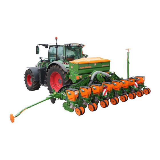
- Page 1 Operating Manual Precision airplanter ED 302 ED 452 ED 452-K ED 602-K MG 5104 Please read this operating BAH0023.0 03.14 manual before commissioning. Keep it in a safe place for future use.
- Page 2 Foreword Reading the instruction manual and to adhere to it should not appear to be inconvenient and superfluous as it is not enough to hear from others and to realise that a machine is good, to buy it and to believe that now everything would work by itself.
- Page 3 + 49 (0) 5405 501-234 E-mail: amazone@amazone.de Spare part orders Spare parts lists are freely accessible in the spare parts portal at www.amazone.de. Please send orders to your AMAZONE dealer. Formalities of the operating manual Document number: MG 5104 Compilation date: 03.14 ©...
- Page 4 Send us your suggestions by fax. AMAZONEN-WERKE H. DREYER GmbH & Co. KG Postfach 51 D-49202 Hasbergen, Germany Tel.: + 49 (0) 5405 50 1-0 Fax: + 49 (0) 5405 501-234 E-mail: amazone@amazone.de ED 02 BAH0023.0 03.14...
-
Page 5: Table Of Contents
2.16.7 Cleaning, maintenance and repair ..................35 Loading and unloading ................36 Loading the precision airplanters ED 302 and ED 452 ............36 Loading the precision airplanters ED 452-K and ED 602-K ..........37 Product description ...................38 Main assemblies of the implement ..................38 Overview of the assemblies .................... - Page 6 Table of Contents Layout and function .................. 53 Classic sowing unit ........................ 54 Contour sowing unit ....................... 55 Seed dosing ........................... 58 Markers ..........................60 Wheel mark eradicator (optional)................... 60 Under root fertilising (optional) ....................61 5.6.1 Fertiliser coulters........................61 Electronic monitoring and operation (optional) ..............
- Page 7 Use of the implement ................162 10.1 Starting work ........................164 10.2 Track marker transport lock (ED 302 and ED 452 [-K]) ............165 10.3 Fold the implement booms ....................165 10.3.1 Folding the implement booms and track markers (ED 452-K and ED 602-K) ....166 10.4...
- Page 8 Table of Contents 11.2 Track marker boom shears off ..................... 169 11.3 Application / calibration fertiliser metering cannot be adjusted ........... 170 11.4 Seed application amount ..................... 172 11.5 Implement boom locks (ED 452-K) ..................172 Maintenance, repairs and servicing ............173 12.1 Cleaning the implement .......................
-
Page 9: User Information
User Information User Information The User Information section provides information on use of the operating manual. Purpose of the document This operating manual • describes the operation and maintenance of the implement, • provides important information about safe and efficient handling of the implement, •... -
Page 10: General Safety Instructions
General Safety Instructions General Safety Instructions This section contains important information on safe operation of the implement. Obligations and liability Comply with the instructions in the operating manual Knowledge of the basic safety information and safety regulations is a basic requirement for safe handling and fault-free implement operation. - Page 11 General Safety Instructions Risks in handling the implement The implement has been constructed to the state-of-the art and the recognised rules of safety. However, operating the implement may cause risks and restrictions to • the health and safety of the user or third parties, •...
-
Page 12: Representation Of Safety Symbols
General Safety Instructions Representation of safety symbols Safety instructions are indicated by the triangular safety symbol and the highlighted signal word. The signal word (danger, warning, caution) describes the severity of the risk, and carries the following meaning: DANGER Indicates an immediate high risk which will result in death or serious physical injury (loss of body parts or long term damage) if not avoided. -
Page 13: Organisational Measures
General Safety Instructions Organisational measures The operator must provide the necessary personal protective equipment as per the information provided by the manufacturer of the crop protection agent to be used, such as: • Safety glasses; • Protective shoes • Chemical-resistant overalls, •... -
Page 14: User Training
General Safety Instructions User training Only trained and instructed persons should be allowed to work with/on the implement. The responsibilities of the operating and maintenance personnel must be clearly defined. People being trained may only work with/on the implement under the supervision of an experienced person. -
Page 15: Safety Measures In Normal Operation
General Safety Instructions Safety measures in normal operation Only operate the implement if all the safety and protection equipment is fully functional. Check the implement at least once a day for visible damage and check the function of the safety and protection equipment. Danger from residual energy Note that there may be residual mechanical, hydraulic, pneumatic and electrical/electronic energy on the implement. -
Page 16: Design Changes
Immediately replace any implement parts which are not in a perfect state. Only use genuine AMAZONE spare and wear parts, or those approved by AMAZONEN-WERKE, so that the type approval remains valid according to the national and international regulations. The use... -
Page 17: Warning Symbols And Other Signs On The Implement
General Safety Instructions 2.13 Warning symbols and other signs on the implement Always keep all the warning pictograms of the implement clean and in a legible state. Replace illegible warning pictograms. You can obtain the warning pictograms from your dealer using the order number (e.g. MD 075). - Page 18 General Safety Instructions Order No. and explanation Warning symbols MD 076 Risk of drawing-in/entrapment for hand or arm due to moving force-transmission parts! This hazard can cause extremely serious injuries resulting in the loss of limbs. Never open or remove protective equipment •...
- Page 19 General Safety Instructions MD 082 Risk of falling caused by riding on the step surfaces or platforms! This risk can cause the most serious injuries with potentially fatal injuries. It is forbidden to carry persons on the implement or to climb on running implements.
- Page 20 General Safety Instructions MD 086 Risk of crushing the entire body due to necessary periods spent under raised, unsecured implement parts. Causes serious, potentially fatal injuries anywhere on the body. Before spending time in the danger area underneath raised implement parts, secure the raised parts to prevent them from being accidentally lowered.
- Page 21 General Safety Instructions MD 093 Risk of entanglement or being dragged in for the whole body by unprotected, driven drive shafts! This risk can cause the most serious injuries to the whole body, potentially even death. Never open protective devices on drive shafts while the tractor engine is running with the PTO shaft connected or the hydraulic drive connected.
- Page 22 General Safety Instructions MD 097 Risk of crushing the entire body due to standing in the stroke area of the three-point suspension when the three-point hydraulic system is actuated. Causes serious, potentially fatal injuries anywhere on the body. • Personnel are prohibited from entering the stroke area of the three-point suspension when the three-point hydraulic system is actuated.
-
Page 23: Positions Of Warning Symbols And Other Labels
General Safety Instructions 2.13.1 Positions of warning symbols and other labels Warning symbols The following diagrams show the arrangement of the warning symbols on the implement. Precision airplanter ED 302 Fig. 1 Fig. 2 ED 02 BAH0023.0 03.14... - Page 24 General Safety Instructions Precision airplanters ED 452 [-K] and ED 602-K Fig. 3 Fig. 4 ED 02 BAH0023.0 03.14...
-
Page 25: Potential Risks From Not Observing The Safety Instructions
General Safety Instructions 2.14 Potential risks from not observing the safety instructions Non-compliance with the safety information • can pose both a danger to people and to the environment and implement. • can lead to the loss of all warranty claims. In particular, non-compliance with the safety information could pose the following risks: •... -
Page 26: Safety Information For Users
General Safety Instructions 2.16 Safety information for users WARNING Risk of crushing, cutting, being trapped or drawn in, or impact through inadequate roadworthiness and operational safety. Before starting up the implement and the tractor, always check their traffic and operational safety. 2.16.1 General safety and accident prevention information •... - Page 27 General Safety Instructions unintentional raising or lowering is impossible, before connecting the implement to or disconnecting the implement from the tractor's three-point hydraulic system. • When coupling and uncoupling implements, move the support equipment (if available) to the appropriate position (stability). •...
- Page 28 General Safety Instructions Use of the implement • Before starting work, ensure that you understand all the equipment and actuation elements of the implement and their function. There is no time for this when the implement is already in operation. •...
- Page 29 General Safety Instructions the approved axle and support loads of the tractor. • The tractor must guarantee the prescribed brake delay for the loaded vehicle combination (tractor plus connected implement). • Check the brake power before moving off. • When turning corners with the implement connected, take the broad load and balance weight of the implement into account.
-
Page 30: Hydraulic System
• Replace the hydraulic hose line if it is damaged or worn. Only use genuine AMAZONE hydraulic hose lines! • The hydraulic hose lines should not be used for longer than six years. This period includes any storage time of a maximum of two years. -
Page 31: Electrical System
General Safety Instructions 2.16.3 Electrical system • When working on the electrical system, always disconnect the battery (negative terminal). • Only use the prescribed fuses. If fuses are used that are too highly rated, the electrical system will be destroyed – risk of fire •... -
Page 32: Attached Tools
General Safety Instructions 2.16.4 Attached tools • When attaching to the three-point linkage, the linkage categories on tractor and implement must be compatible or an adapter must be used! • Take note of the manufacturer's instructions. • Before attaching implements to or removing them from the three- point suspension, shift the operating equipment to a position in which unintended raising or lowering is impossible. -
Page 33: Pto Shaft Operation
General Safety Instructions 2.16.5 PTO shaft operation • Use only the PTO shafts prescribed by the AMAZONEN-WERKE factories, equipped with the proper safety devices. • Also read and follow the operating manual from the PTO shaft manufacturer. • The protective tube and PTO shaft guard must be undamaged, and the shield of the tractor and implement universal joint shaft must be attached and be in proper working condition. -
Page 34: Operation Of The Seed Drill
General Safety Instructions universal joint shaft stub. • When using the travel-dependent universal joint shaft, note that the universal joint shaft speed depends on the drive speed, and that the direction of rotation reverses when you drive in reverse. 2.16.6 Operation of the seed drill •... -
Page 35: Cleaning, Maintenance And Repair
• Spare parts must comply at least with the specified technical requirements of AMAZONEN-WERKE. This is ensured through the use of genuine AMAZONE spare parts! ED 02 BAH0023.0 03.14... -
Page 36: Loading And Unloading
Loading and unloading Loading and unloading DANGER Never stand underneath implements lifted by a crane. Loading the precision airplanters ED 302 and ED 452 The precision airplanters ED 302 and ED 452 are loaded with a crane (Fig. 5). Fig. 5 Fasten the transport straps (Fig. -
Page 37: Loading The Precision Airplanters Ed 452-K And Ed 602-K
Loading and unloading Loading the precision airplanters ED 452-K and ED 602-K Fold in the precision airplanters ED 452-K and ED 602-K and load as follows with a crane. 1. Fasten the transport straps (Fig. 7/1) to the eyelets on the implement Fig. -
Page 38: Product Description
Product description Product description This section: • provides a comprehensive overview of the implement's structure • provides the names of the individual modules and controls. If possible, read this section when actually at the implement. This helps you to understand the implement better. Main assemblies of the implement Fig. - Page 39 Product description Fig. 10 Fig. 10/... (1) Universal joint shaft for the fan drive (2) Drive wheels (3) Setting gearbox ED 02 BAH0023.0 03.14...
-
Page 40: Overview Of The Assemblies
Product description Overview of the assemblies Fig. 11 AMASCAN control terminal (optional) Fig. 11 Fig. 12 AMASCAN-PROFI control terminal (optional) Fig. 12 Fig. 13 ED-CONTROL control terminal (optional) Fig. 13 ED 02 BAH0023.0 03.14... - Page 41 Product description Classic sowing unit Fig. 14/... (1) Seed hopper (2) Adjusting the seed placement depth (3) Sowing housing (4) Seeding coulter (5) Farm flex tyre (6) Leading closer Fig. 14 Contour sowing unit Fig. 15/... (1) Seed hopper (2) Adjusting the seed placement depth (3) Sowing housing (4) Seeding coulter (5) Leading press roller...
-
Page 42: Safety And Protection Equipment
Product description Safety and protection equipment Fig. 18/... (1) PTO shaft guard Fig. 18 Fig. 19/... (1) Fan guard Fig. 19 Fig. 20/.. (1) Exhaust air guide ENVIRO-Safe Fig. 20 ED 02 BAH0023.0 03.14... -
Page 43: Transportation Equipment (Optional)
Product description Transportation equipment (optional) Fig. 21/... (1) 2 rear-facing turn signals (2) 1 light for 1 number plate holder (optional) (3) 2 red reflectors (4) 2 brake and tail lamps (5) 2 rear-facing warning signs (6) 2 reflectors, yellow. Fig. -
Page 44: Intended Use
Compliance with all the instructions in this operating manual • Adherence of inspection and maintenance work • Exclusive use of genuine AMAZONE spare parts. Other uses to those specified above are forbidden and shall be considered as improper. For any damage resulting from improper use •... -
Page 45: Danger Areas And Danger Points
Product description Danger areas and danger points The danger area is the area around the implement in which people can be caught by: • work movements made by the implement and its tools • materials or foreign bodies thrown out of the implement •... -
Page 46: Rating Plate And Ce Mark
EU directives. Fig. 23 The following illustrations show the arrangement of the rating plate and the CE mark on the implements • ED 302, ED 452 (-K) (see Fig. 24) • ED 602-K (see Fig. 25). Fig. 24 Fig. 25... -
Page 47: Necessary Tractor Equipment
4.8.1 Tractor engine power without fertiliser hopper with fertiliser hopper ED 302 from 44 kW (60 HP) from 55 kW (75 HP) ED 452 / ED452-K from 55 kW (75 HP) from 66 kW (90 HP) -
Page 48: Overview - Supply Lines Between The Tractor And The Implement
Product description Overview - Supply lines between the tractor and the implement 4.9.1 Hydraulic standard circuit Fig. 26 Implement side Tractor side Run direction Marking Function single Yellow Feed Track marker actuation (T/S) acting Feed line double only ED02-K: Green acting Boom folding system, left side (T) (2a) -
Page 49: Hydraulic Profi Control (Without Load-Sensing Function)
Product description 4.9.2 Hydraulic Profi control (without load-sensing function) Fig. 27 Implement side Tractor side Run direction Marking Function Tractor control unit Feed Profi control without double-action load-sensing function unpressurised lines (1a) Return line Tractor control unit single or double- Feed line action Hydraulic motor blower... -
Page 50: Hydraulic Profi Control (With Load-Sensing Function)
Product description 4.9.3 Hydraulic Profi control (with load-sensing function) Fig. 28 Implement side Tractor side Run direction Marking Function Feed: LS pressure line Profi control Return flow: Tractor control unit (1a) with load-sensing "LS" Pressure-free tank line function LS control line 4.10 Noise production data The workplace-related emission value (acoustic pressure level) is 74... -
Page 51: Technical Specifications
Product description 4.11 Technical specifications Precision airplanter ED 302 ED 452 Sowing units Classic Contour Classic Contour Possible tyres 10.0/75-15 Transport width 3.00 4.00 (also see table Seite 91) Transport length 2.40 2.40 Number of sowing units in standard version (row spacing 75 cm) Max. -
Page 52: Technical Data For Calculating The Tractor Weight And The Tractor Axle Loads
(see Seite 67) Total weight G Distance d 4-row classic 802 kg 885 mm ED 302 without fertiliser hopper 4-row contour 942 kg 1076 mm 10-row classic 1372 kg 1070 mm... -
Page 53: Layout And Function
Track markers (Fig. 29/6) mark the field connection run either in the centre of the tractor in the tractor track (except ED 302). For under root fertilising (optional), precision airplanters are fitted with fertiliser coulters (Fig. 29/7) which deposit the fertiliser normally at 6 cm distance (adjustable) next to the seeding coulters (Fig. -
Page 54: Classic Sowing Unit
Layout and function Classic sowing unit The classic sowing unit is used for sowing in ploughed ground. Seed which can be sown with the classic sowing unit: • • Maize Peas • • Beans Cotton • • Sunflowers Sorghum The crank (Fig. 30/1) is used to adjust the seed placement depth. -
Page 55: Contour Sowing Unit
Layout and function Contour sowing unit Sowing process with the contour sowing unit: • Conventional sowing • Mulch sowing Seed which can be sown with the contour sowing unit: • • Maize Sugar beet • • Beans Turnips • • Sunflowers Rapeseed •... - Page 56 Layout and function The large double discs (Fig. 34/1) clear the organic remains of plants from fields in front of the seeding coulter (Fig. 34/2). The rubber V-press roller (Fig. 34/3) and the super V-press roller are suitable for plowing and mulch sowing.
- Page 57 Layout and function The clod clearer (Fig. 37/1) allows the sowing unit to run smoothly on ground with rough surface structures. Do not insert the clod clearer too deeply. The clod clearer should only clear the large clods off to the side. If the clod clearer causes complete earth movement, this has a negative impact when closing the seed furrows.
-
Page 58: Seed Dosing
Layout and function Seed dosing At a set row spacing, sowing is wanted at a certain number "grains per m " or "grains per hectare". The required grain spacing is calculated from this which is set by adjusting the speed of the singling discs. - Page 59 Layout and function An ejector (Fig. 43/1) releases any broken grains which could block up the holes of the singling disc. If several seeds are sucked into a hole at the same time, an adjustable scraper (5 positions, Fig. 43/2) carefully wipes off the excess seed grains which then fall back into the seed hopper area (Fig.
-
Page 60: Markers
Layout and function Markers The hydraulically-actuated track markers (Fig. 47/1) dig into the ground alternately on the left and the right of the implement. In so doing, the active track marker creates a mark. This mark serves as an orientation aid for the next run after turning. -
Page 61: Under Root Fertilising (Optional)
Layout and function Under root fertilising (optional) 5.6.1 Fertiliser coulters The fertiliser placement depth and the distance between the fertiliser coulters to the seeding coulters is adjustable. Obstacles are avoided by the fertiliser coulters. The towed fertiliser coulters (Fig. 49) are used •... -
Page 62: Electronic Monitoring And Operation (Optional)
Layout and function Electronic monitoring and operation (optional) The precision airplanters are electronically monitored and controlled via an on-board computer (optional). There are three on-board computers available for the different requirements: • AMASCAN • AMASCAN-PROFI • ED-CONTROL. The display and operation is done using the control terminal in the tractor cabin. -
Page 63: Amascan-Profi
Layout and function 5.7.2 AMASCAN-PROFI The AMASCAN-PROFI has all the functions of the AMASCAN and also has the additional functions listed below: • folds the sowing unit booms in and out separately • folds the track markers in and out separately •... -
Page 64: Start-Up
Start-up Start-up This section contains information • on initial operation of your implement • On checking how you may couple the implement to your tractor. • Before operating the implement for the first time the operator must have read and understood the operating manual. •... -
Page 65: Checking The Suitability Of The Tractor
Start-up Checking the suitability of the tractor WARNING Danger of breaking during operation, insufficient stability and insufficient tractor steering and braking power on improper use of the tractor! • Check the suitability of your tractor before you attach or hitch the implement to the tractor. -
Page 66: Calculating The Actual Values For The Total Tractor Weight, Tractor Axle Loads And Load Capacities, As Well As The Minimum Ballast
Start-up 6.1.1 Calculating the actual values for the total tractor weight, tractor axle loads and load capacities, as well as the minimum ballast The approved total tractor weight, specified in the vehicle documentation, must be greater than the sum of the •... -
Page 67: Data Required For The Calculation (Attached Implement)
Start-up 6.1.1.1 Data required for the calculation (attached implement) Fig. 54 [kg] Tractor empty weight See tractor operating manual or vehicle documentation [kg] Front axle load of the empty tractor [kg] Rear axle load of the empty tractor [kg] Total weight of rear-mounted implement or See section "Technical specifications"... -
Page 68: Calculation Of The Required Minimum Ballasting At The Front G Steering Capability
Start-up 6.1.1.2 Calculation of the required minimum ballasting at the front G of the tractor to V min ensure steering capability • − • • • Enter the numeric value for the calculated minimum ballast G V min required on the front side of the tractor, in the table (section 6.1.1.7). 6.1.1.3 Calculation of the actual front axle load of the tractor T V tat... -
Page 69: Table
Start-up 6.1.1.7 Table Actual value according to Approved value Double approved calculation according to tractor load capacity (two instruction manual tyres) Minimum ballast front / rear ≤ Total weight ≤ ≤ Front axle load ≤ ≤ Rear axle load • You can find the approved values for the total tractor weight, axle loads and load capacities in the tractor registration papers. -
Page 70: Securing The Tractor / Implement Against Unintentional Start-Up And Rolling
Start-up Securing the tractor / implement against unintentional start-up and rolling WARNING Risk of crushing, shearing, cutting, being caught and/or drawn in, or impact when making interventions in the implement, through • Unintentional lowering of the unsecured implement when it is raised via the three-point hydraulic system of the tractor •... -
Page 71: Adjust The Pto Shaft To The Tractor
Start-up 6.2.1 Adjust the PTO shaft to the tractor Prior to the first coupling to the tractor and when changing the tractor adjust the PTO shaft length. In this regard, observe the operating manual of the PTO shaft manufacturer. DANGER Only install / remove the PTO shaft with the drive shaft turned off, the hand brake applied, the engine switched off and the ignition key removed. -
Page 72: Installation Regulations For The Hydraulic Blower Fan Drive Connection (Optional)
Start-up 6.2.2 Installation regulations for the hydraulic blower fan drive connection (optional) The banking-up pressure of 10 bar must not be exceeded. The installation regulations therefore have to be complied with when connecting the hydraulic fan connection. • Connect the hydraulic coupling of the pressure line (Fig. 56/5) to a single-acting or double-acting tractor control unit with priority. -
Page 73: Installation Regulations Profi Control (Optional)
Start-up 6.2.3 Installation regulations Profi control (optional) Without "LS operation": • Connect the pressure line (Fig. 57/2) to a single or double- acting tractor control unit with priority. With "LS operation": • LS pressure line connection • LS control line connection. With and without "LS operation": •... -
Page 74: Initial Installation Of The Control Terminal (Optional)
Start-up Profi controls with load sensing function are marked with a "LS" sticker (Fig. 58/1). Fig. 58 6.2.4 Initial installation of the control terminal (optional) The initial installation of the control terminal (Fig. 59) in the tractor cabin can be taken from the respective operating instructions. -
Page 75: Initial Installation Of The Clod Clearer (Optional, Contour Sowing Unit)
Start-up 6.2.5 Initial installation of the clod clearer (optional, contour sowing unit) 1. Screw in the guide bolts (Fig. 60/1). Fig. 60 2. Hang the clod clearer (Fig. 61/1) on the guide bolts (Fig. 60/1), secure with a pin (Fig. 61/2) and secure with a linch pin. Fig. -
Page 76: Coupling And Uncoupling The Implement
Coupling and uncoupling the implement Coupling and uncoupling the implement When coupling and uncoupling the implement take heed of the section "Safety information for users", Seite 26. WARNING Risk of contusions from unintentional starting and rolling of the tractor and implement when coupling or uncoupling the implement! Secure the tractor and implement to prevent unintentional starting and rolling before entering the danger area between the tractor and... - Page 77 Coupling and uncoupling the implement WARNING Risk of contusions, cutting, catching, drawing in and knocks when the implement unexpectedly releases from the tractor! • Use the intended equipment to connect the tractor and the implement in the proper way. • When coupling the implement to the tractor's three-point hydraulic system, it is vital to ensure that the tractor mount categories of the tractor and the implement are the same.
-
Page 78: Coupling The Implement
Coupling and uncoupling the implement Coupling the front tank Couple and uncouple the front tank (Fig. 62) to the tractor based on the front tank's operating instructions. Fig. 62 Create a conducting connection of the front tank's cable harness (implement plug) to the tractor ground (danger of static charging). Coupling the implement 1. - Page 79 Coupling and uncoupling the implement 5. The implement is fitted with category II lower and top link pins. Fit the lower and top link pins with bearing sleeves (Fig. 64). The bearing sleeves used depend on the type of the tractor (see the tractor's operating instructions).
- Page 80 Coupling and uncoupling the implement 9. Open the tractor lower link securing device, i.e. it must be ready for coupling. 10. Drive the tractor further backwards towards the implement so that the lower link hooks of the tractor automatically take up the lower bearing sleeves of the lower pivot point of the implement.
- Page 81 Coupling and uncoupling the implement DANGER Only install / remove the PTO shaft with the drive shaft turned off, the hand brake applied, the engine switched off and the ignition key removed. If you are caught up in a rotating shaft, it can cause serious injury or even death.
-
Page 82: Hydraulic Connections
Coupling and uncoupling the implement Check the route of the supply lines. The supply lines: • Must easily give way to all movements in bends without tensioning, kinking or rubbing. • Must not chafe against other parts. Hydraulic connections All of the hydraulic hose lines are equipped with grips. Coloured markings with a code number or code letter have been applied to the gripping sections in order to assign the respective hydraulic function to the pressure line of a tractor controller! - Page 83 Coupling and uncoupling the implement Implement side Interfac Identification of the Tractor control unit implement functions hydraulic lines Feed Boom folding system, left side double Green No. 2 acting return Feed Tractor Boom folding system, right double Blue No. 3* acting side (T) return...
-
Page 84: One Control Unit For Two Implement Functions (Control Unit, Optional)
Coupling and uncoupling the implement 7.2.1 One control unit for two implement functions (control unit, optional) If there are fewer tractor control units available than are needed, two implement functions can be assigned to one tractor control unit. Select one of the two functions desired using the lever (Fig. -
Page 85: Electrical Connections
Coupling and uncoupling the implement Implement side Interfac Identification of the Front tractor control unit implement functions hydraulic lines Feed Star wheel lifting double Tractor natural acting front tank (T) return *** not required when connected to ED-CONTROL Profi control with load-sensing function Implement side Interfa Identification of the... -
Page 86: Supports
Coupling and uncoupling the implement Supports DANGER The implement may only be set down on a level, firm surface. Before pinning the support legs, apply the hand brake, switch off the tractor engine, and remove the ignition key. When detached, the implement is supported on two support legs. Support position: Pin the support leg (Fig. -
Page 87: Uncoupling The Implement
Coupling and uncoupling the implement Uncoupling the implement WARNING Risk of contusions, cutting, catching, drawing in and knocks through insufficient stability and possible tilting of the uncoupled implement! Set the empty implement down on a level parking area with a firm base. - Page 88 Coupling and uncoupling the implement 6. Uncouple the top link from the tractor seat. 7. Uncouple the lower link from the tractor seat. 8. Pull the tractor forwards. Fig. 72 ED 02 BAH0023.0 03.14...
-
Page 89: Settings
Settings Settings WARNING Risk of crushing, shearing, cutting, being caught and/or drawn in, or impact through • Unintentional falling of the implement raised using the tractor's three-point hydraulic system. • unintentional lowering of raised, unsecured implement parts. • Unintentional starting and rolling of the tractor-implement combination. -
Page 90: Adjust The Row Spacing
Settings Adjust the row spacing 1. Undo the bolts (Fig. 73/1) and nuts (Fig. 73/2). 2. Lift up the implement and support with suitable supports. 3. The sowing unit can be adjusted to the desired row spacing by sliding the sowing unit on the clamping rail (Fig. -
Page 91: Adjustable Row Spacings
Transport rows spacing sowing units fertiliser width (m) width (m) units fertiliser width (m) width (m) possible possible ED 302 2.80 3.00 2 right / 2 left 2.80 3.00 3.00 3.00 2 right / 2 left 3.00 3.00 3.20 3.00 2 right / 2 left 3.20... -
Page 92: Adjusting The Track Width
Settings Adjusting the track width To avoid driving over the seed bed, the track width can be adjusted using the various attachment positions to the row width. If the row width is 70, 75, or 80 cm, fit the wheel on the inside flange Fig. -
Page 93: Switching Off The Sowing Units
Settings Switching off the sowing units When not being used, or for maintenance purposes, the sowing units can be switched off. This switching off is done mechanically, or electronically as an optional. Interrupt the fertiliser feed (if present) to the associated fertiliser coulters. -
Page 94: Grain Spacing
Settings Grain spacing At a set row spacing and with the prescribed singling discs, sowing is wanted as a certain number of "grains per m " or "grains per hectare". 8.5.1 Grain spacing (tabular) Find the required grain spacing from the tables from Seite 95. Example: Singling discs: 30 bore holes... - Page 95 Settings Singling discs with 15 boreholes Row spacing Grain distance a Grain/m 80 cm 75 cm 70 cm 60 cm 50 cm 45 cm 37.5 cm 30 cm (cm) Number of grains per hectare 12.2 102459 109290 117103 136612 163934 182149 218580 273224...
- Page 96 Settings Singling discs with 30 boreholes Row spacing Grain distance a Grain/m 80 cm 75 cm 70 cm 60 cm 50 cm 45 cm 37.5 cm 30 cm (cm) Number of grains per hectare 16.4 204918 218579 234204 273224 327869 364299 437158 546448...
- Page 97 Settings Singling discs with 45 boreholes Row spacing Grain distance a Grain/m 80 cm 75 cm 70 cm 60 cm 50 cm 45 cm 37.5 cm 30 cm (cm) Number of grains per hectare 24.4 304878 325203 348450 406504 487805 542005 650406 813008...
- Page 98 Settings Singling discs with 60 boreholes Row spacing Grain distance a Grain/m 80 cm 75 cm 70 cm 60 cm 50 cm 45 cm 37.5 cm 30 cm (cm) Number of grains per hectare 32.8 409836 437158 468409 546448 655738 728597 874316 1092896...
- Page 99 Settings Singling discs with 90 boreholes Row spacing Grain distance a Grain/m 80 cm 75 cm 70 cm 60 cm 50 cm 45 cm 37.5 cm 30 cm (cm) Number of grains per hectare 48.8 609756 650407 696902 813008 975610 1084011 1300814 1626016...
-
Page 100: Grain Spacing (Calculated)
Settings 8.5.2 Grain spacing (calculated) Grain distance a [cm] Grains per m² x row spacing [m] Example: Number of boreholes of the singling disc: 30 bore holes Desired "number of grains per hectare": 95000 grains/ha (= 9.5 grains per m²) Selected row spacing: 0.75m Grain distance a [cm]... - Page 101 Settings Example: Singling discs: 30 boreholes Grain spacing a: 13.9 cm The gear ratio can be taken from the table (as seen in Fig. 80): Chain wheel pairing A – 3 in the setting gearbox: Chain wheel pairing in the secondary gearbox: Fig.
-
Page 102: Set The Grain Spacing In The Setting Gearbox
Settings Set the grain spacing in the setting gearbox The following section describes how the gear ratio determined is set in the implement. The grain spacing is adjustable in the setting gearbox (Fig. 40/1). 1. Remove the hooks (Fig. 81/1) from the holder. - Page 103 Settings CAUTION The spring pressure which is applied to the hand crank is very large. 4. Release the tension of the chain tensioner using the hand crank (Fig. 84). 5. Press the hand crank (Fig. 83/1) so far that the pin (Fig. 85/1) engages into the recess (Fig.
- Page 104 Settings 7. Using the hook(Fig. 81/1), place the roller chain (Fig. 86/7) onto the correct chain cog. → Setting value, see section "Chain wheel pairs for the setting and secondary gearboxes", Seite 100. Example: Chain cog pairing A – 3. The roller chain connects the chain cog (Fig.
- Page 105 Settings CAUTION The large spring pressure acts immediately after loosening the bolts on the hand crank. 9. Press the hand crank and the links at the same time in the direction of the arrow (Fig. 88). Lever out the link on the bolt out of the recess (Fig.
-
Page 106: Adjusting The Grain Spacing In The Secondary Gearbox
Settings Adjusting the grain spacing in the secondary gearbox 1. Unscrew the wing nut (Fig. 89/1). 2. Remove the gearbox cover (Fig. 89/2). Fig. 89 3. Latch the lever (Fig. 90/1) in the groove (Fig. 90/2). → The roller chain relaxes. Fig. - Page 107 Settings 4. Loosen the wing nut (Fig. 91/1) and slide the chain tensioner to the back. Fig. 91 5. Using the hook (Fig. 81/1) lay the roller chain (Fig. 92) onto the correct chain cog (X, Y, or Z). Setting value, see section "Chain wheel pairs for the setting and secondary gearboxes", Seite 100.
-
Page 108: Adapting The Sowing Unit To The Seed
Settings Adapting the sowing unit to the seed Sowing unit setting data • • • the singling disc Ejector Position • Thousand grain weight • Seed < 220 g 30/5 Green 910777 black 926240 (11 kg / 50000 G) 220 to 250 g 30/5 Green 910777... -
Page 109: Determining Grain Size
Settings 8.8.1 Determining grain size Using the multi-placement tester, the singling can be adapted to the seed. Fig. 94 1. By placing the seed on the comparison holes (Fig. 95/1), the optimum hole diameter can be determined. Fig. 95 8.8.2 Checking the placement depth and grain spacing Different soils have an effect on the seed placement depth and the grain spacing. -
Page 110: Adapting The Sowing Unit To The Seed
Settings 8.8.3 Adapting the sowing unit to the seed The following section describes how the settings of the sowing unit are adapted to the seed. 8.8.3.1 Adjusting the scraper Secure the implement with suitable supports to prevent unintentional sinking! The scraper positions 1 to 5 can be seen on the adjusting lever (Fig. -
Page 111: Set The Reduction Flap
Settings 5. Pull off the suction cover (Fig. 98/4) together with the singling disc (Fig. 99/1) from the sowing housing. 6. If required, change the singling disc. Fig. 99 Important The naps (Fig. 99/2) point towards the sowing housing, not the suction cover. -
Page 112: Close The Sowing Housing
Settings Parking the reduction flap To deactivate the reduction flap's function (Fig. 102/2), change the adjustment. 1. Undo and remove the fixing bolts (Fig. 102/1), 2. Turn the reduction flap (Fig. 102/2) upwards and set it in the upper position (Fig. 102/3), 3. -
Page 113: Check The Scraper Position And The Reduction Flap Position
Settings 8.8.4 Check the scraper position and the reduction flap position 1. Fill the seed hopper (see section "Filling and emptying the seed hopper", Seite 114). 2. Switch on the blower fan (see section "Blower fan speed", Seite 116). 3. Turn the drive wheel (Fig. 168) and thereby the singling discs with the hand crank. -
Page 114: Filling And Emptying The Seed Hopper
Settings 6. If there are still grains missing with the scraper correctly set on the holes of the singling disc, increase the size of the opening by adjusting the reducing flap (Fig. 107/1) to the next lowest position number. If seed appears out of the housing opening (Fig. - Page 115 Settings Emptying the seed hopper and sowing housing WARNING Only hold the spring-loaded flap (Fig. 110/2) on its handle (Fig. 110/3), otherwise there is a risk of injury if the flap snaps closed. Never reach between the flap and the sowing housing with your hand.
-
Page 116: Coulter Tips
Settings 8.10 Coulter tips When changing from maize seed to beet/turnip seed, the coulter tips on the contour sowing unit should be exchanged (see section "Check / exchange the seeding coulter tips", Seite 189). The required coulter tips can be found in the table (Fig. 112). Maize coulter tips Beet/turnip coulter tips (for classic and contour sowing unit) -
Page 117: Pto Blower Fan Drive
Settings Notes for setting the fan speed on the front tank (see section "Adjusting the fan speed on the front tank", Seite 120). The compressed air fan and the suction fan have the same speed. The pressure gauge (Fig. 113) shows the vacuum of the suction fan. -
Page 118: Hydraulic Blower Fan Drive
Settings 8.11.2 Hydraulic blower fan drive The blower fan can be driven by a hydraulic motor (Fig. 116). The fan speed can be set via the pressure gauge (Fig. 113), either: • on the flow control valve of the tractor (if fitted) (see section "Adjusting the fan speed", Seite 119) •... -
Page 119: 8.11.2.1 Adjusting The Fan Speed Via The Flow Control Valve Of The Tractor
Settings 8.11.2.1 Adjusting the fan speed via the flow control valve of the tractor 1. Fill all seed hoppers. 2. Unscrew the lock nut (Fig. 117/1). 3. Close the hand wheel (Fig. 117/2) (turn clockwise) and finally open it by 1/2 a turn so that the oil supply amount is as small as possible. -
Page 120: 8.11.2.3 Adjusting The Fan Speed On The Front Tank
Settings 8.11.2.3 Adjusting the fan speed on the front tank The combinations with front tanks have two fans • the exhaust fan on the precision airplanter • the compressed air fan on the front tank. Adjust the fan speed of the exhaust fan (see section "Blower fan speed", Seite 116). -
Page 121: Adjusting The Track Marker
Settings 8.12 Adjusting the track marker Danger It is forbidden to stand in the swivelling area of the track marker! Carry out the adjustments to the track marker only with the hand brake applied, the engine switched off and the ignition key removed. 8.12.1 Calculating the track marker length to mark a track in the centre of the tractor Calculating the track marker width A (Fig. -
Page 122: Calculating The Track Marker Length To Mark A Track In The Tractor Track
Settings 8.12.2 Calculating the track marker length to mark a track in the tractor track Calculating the working width A (Fig. 121) measured from the centre of the implement to the contact surface of the track marker disc on the ground with the coulters arranged symmetrically. -
Page 123: Adjusting The Track Marker (Ed 302)
Settings 8.12.4 Adjusting the track marker (ED 302) The track markers of the ED 302 mark a track in the centre of the tractor. Adjusting the track marker length: 1. Set the implement down on the field. 2. Release the track markers (see section "Track marker transport lock", Seite 165). -
Page 124: Adjusting The Track Marker (Ed 452 [-K])
Settings 8.12.5 Adjusting the track marker (ED 452 [-K]) The track markers of the ED 452 [-K] mark a track in the centre of the tractor or in the tractor track. Adjusting the track marker length: 1. Set the implement down on the field. 2. -
Page 125: Adjusting The Track Marker (Ed 602-K)
Settings 8.12.6 Adjusting the track marker (ED 602-K) The track markers of the ED 602-K mark a track in the centre of the tractor or in the tractor track. Adjusting the track marker length: 1. Set the implement down on the field. 2. -
Page 126: Adjusting The Wheel Mark Eradicator
Settings 10. Loosen the turnbuckle lock nut (Fig. 130/1). 11. Adjust the turnbuckle so that the track marker disc (Fig. 129/2) touches the ground. 12. Shorten the turnbuckle by one turn so that the working depth of the track marker disc is limited to approximately 5 cm. - Page 127 Settings Before moving the wheel mark eradicator • Horizontally: loosen nut (Fig. 132/1) • Vertically: loosen the linch pin and bolt (Fig. 132/2). Fig. 132 ED 02 BAH0023.0 03.14...
-
Page 128: Adjusting The Seed Placement Depth (Classic Sowing Unit)
Settings 8.14 Adjusting the seed placement depth (classic sowing unit) Set the seed hopper cover horizontally be lengthening or shortening the top link. Bring the implement to the working position in the field (see section "Use of the implement", Seite 162). Release the spring clip (Fig. -
Page 129: Adjusting The Loading Level (Classic Sowing Unit)
Settings 8.14.1 Adjusting the loading level (classic sowing unit) Caution! Risk of injury when releasing the spring-loaded lever (Fig. 134). 1. Lift up the implement on the tractor three- point hitch far enough so that the sowing units are clear of the ground. 2. -
Page 130: Adjusting The Seed Placement Depth (Contour Sowing Unit)
Settings 8.15 Adjusting the seed placement depth (contour sowing unit) 1. Put the implement in the working position in the field (see Chapter "Use of the implement", Seite 162). 2. Release the spring clip (Fig. 135/1). The spring clip secures the crank (Fig. 135/2) from turning. - Page 131 Settings Hang both draw springs (Fig. 136/4) as shown in figures (Fig. 137 to Fig. 139). Using the hand crank, tension the springs and hang the struts (Fig. 136/2), as shown in figures (Fig. 137 to Fig. 139) on one bolt. Perform the fine adjustment of the placement depth with the crank [see section "Adjusting the seed placement depth", Seite...
-
Page 132: Setting The Load Distribution Of The Press Rollers (Contour Sowing Unit)
Settings 8.15.2 Setting the load distribution of the press rollers (contour sowing unit) To adapt to the various soil properties and conditions, the load distribution between the front-running (Fig. 141/1) and the rear-running press rollers (Fig. 141/2) is adjustable. If the seed furrow cannot be closed due to the hardness of the soil, more load should be applied to the rear farm flex tyres to break the furrow edges and to close the seed furrow. -
Page 133: Adjusting The Clod Clearer (Contour Sowing Unit)
Settings In each of the positions "A" to "C", the weight which is applied to the rear V-press roller (Fig. 142/1) can be changed with the lever (Fig. 142/2). Depending on how high the lever is inserted into the holder, the larger the force which acts upon the trailing press roller. -
Page 134: Closing The Seed Furrow (Classic Sowing Unit)
Settings 8.17 Closing the seed furrow (classic sowing unit) Follow the implement at the start of work on the field and check the seed coverage. If the seed furrow is not closed, adjust the working intensity of the following closers (Fig. -
Page 135: Closing The Seed Furrow (Contour Sowing Unit)
Settings 8.18 Closing the seed furrow (contour sowing unit) The working intensity of the closer (Fig. 147/1) or the disc closer (Fig. 148/1) increases the higher the lever (Fig. 146/1) is locked into place. Fig. 146 Fig. 148 Fig. 147 The rubber V-press rollers keep the placement depth and closes the seed furrow. -
Page 136: Adjusting The Intermediate Press Roller (Contour Sowing Unit)
Settings If the seed furrow is not closed with the correct setting of the axial distance, the means of working of both angled pressure rollers to each other can be infinitely adjusted using a lever (Fig. 150/2) after the bolted connection (Fig. 150/1) has been released. -
Page 137: Adjusting The Fertiliser Coulters
Settings 8.19 Adjusting the fertiliser coulters 1. Loosen the nut (Fig. 153/1) to move the fertiliser coulter horizonally on the clamping rail. The distance to the seeding coulter is set at the factory to 6 cm. 2. Remove the R clip and the pin (Fig. 153/2) to adjust the placement depth of the fertiliser coulter. -
Page 138: Adjust The Fertiliser Coulters (Ed 602K With 70 Cm Row Spacing)
Settings 8.19.2 Adjust the fertiliser coulters (ED 602K with 70 cm row spacing) A deep depositing setting for the fertiliser coulters with the ED 602-K with 8 rows and 70 cm row spacing can result in a collision between the coulter disc and the setting gearbox during the folding procedure! (See Fig. -
Page 139: Fertiliser Hopper (650, 900 And 1100 L)
Settings 8.20 Fertiliser hopper (650, 900 and 1100 l) Couple the implement to the tractor before filling the fertiliser hopper. Empty the fertiliser hopper before uncoupling the implement from the tractor. 8.20.1 Filling the fertiliser hopper (650, 900 and 1100 l) 1. -
Page 140: Adjusting The Fertiliser Quantity
Settings 8.20.2 Adjusting the fertiliser quantity The maximum application quantity is approx. 550 kg/ha at a working speed of 8 km/h! Test each adjustment with a calibration test (see section "Calibration test", Seite 144). 1. Remove the spray protection (Fig. 160/1). The spray protection is hung on two brackets (Fig. - Page 141 Settings 3. Position the active shutter slides (Fig. 162) in position "B". 4. Position all other shutter slides in position "A". The fertiliser supply to the fertiliser coulters is interrupted. Shutter slide positions (Fig. 162): • A = closed • B = 3/4 open •...
-
Page 142: 8.20.2.1 Determine The Gearbox Setting Number
Settings 8.20.2.1 Determine the gearbox setting number Fig. 164 ED 02 BAH0023.0 03.14... - Page 143 Settings Calculating the gearbox setting number for precision airplanters with other row spacings Row spacing x application rate (table value) Conversion factor Row spacing x application rate Gearbox setting number (table value) Gearbox setting number Conversion factor Example: Desired fertiliser type: di-ammonium phosphate Table value (Fig.
-
Page 144: Emptying The Fertiliser Hopper
Settings 8.20.3 Emptying the fertiliser hopper To empty the fertiliser hopper, remove the hose (Fig. 165/2) from the bracket which is secured with a linch pin (Fig. 165/1). Fig. 165 Fig. 166 8.21 Calibration test (650, 900 and 1100 l hoppers) You can check if the desired fertiliser quantity is being applied using the calibration test. - Page 145 Settings 6. Empty the collecting buckets (not into the fertiliser hopper with the blower fan running). 7. Put the collecting buckets back under the fertiliser coulters. 8. Read the number of crank turns from the table (Fig. 169). The number of crank turns is determined by the working width and the tyres on the implement.
- Page 146 Settings 9. Turn the crank clockwise by the number of crank turns in the table (Fig. 169). 10. Weigh the amount of fertiliser collected taking the weight of the container into consideration (Fig. 171) and multiply by the factor "40". Fig.
-
Page 147: Front Tank
Settings 8.22 Front tank DANGER Couple the front tank to the tractor before filling. Empty the front tank before uncoupling from the tractor. Before filling, check which metering roller is attached. If required, change the metering roller! • Recommended: Polyurethane metering roller •... - Page 148 Settings 3. Loosen, but do not unscrew the two wing nuts (Fig. 174/1) 4. Turn the bearing cover and pull it off. Fig. 174 5. Pull the metering roller out of the dosing unit. 6. Fit the desired metering roller in the reverse sequence.
-
Page 149: Adjusting The Fertiliser Quantity
Settings 8.22.2 Adjusting the fertiliser quantity To apply the desired fertiliser quantity, adjustments have to be made • To the metering units • To the vario gearbox. Fig. 176 Test each adjustment with a calibration test (see section "Calibration test", Seite 154). 1. - Page 150 Settings Di-ammonium phosphate 18 – 46 – 0 Type of fertilizer 0.97 kg/l Type • • • • • • Working width • 4.44 2.22 2.67 • 33.3 16.7 • 64.4 32.2 38.7 • 88.9 44.4 53.3 • 62.2 74.7 •...
- Page 151 Settings Calcium ammonium nitrate Type of fertilizer 1.06 kg/l Type • • • • • • Working width • 3.33 1.67 • 26.7 13.3 • 62.2 31.1 37.3 • 93.3 46.7 • 62.2 74.7 • • 97.8 • • • •...
- Page 152 Settings Type of fertilizer 1.15 kg/l Type • • • • • • Working width • 5.56 2.78 3.33 • • 75.6 37.8 45.3 • • 73.3 • 91.1 • • • • • • • • • • • •...
- Page 153 Settings Urea Type of fertilizer 0.75 kg/l Type • • • • • • Working width • 4.44 2.22 2.67 • 35.6 17.8 21.3 • 62.2 31.1 37.3 • 84.4 42.2 50.7 • 53.3 • 64.4 77.3 • 77.8 93.3 •...
-
Page 154: 8.22.2.1 Calibration Test
Settings 8.22.2.1 Calibration test You can check if the desired fertiliser quantity is being applied using the calibration test. 1. Fill the fertiliser hopper at least 1/4 full with fertiliser.. 2. Take the collection buckets from the transport bracket. The collection buckets are stacked together for transport, and secured with a linch pin (Fig. - Page 155 Settings 5. Insert the hand crank into the square hole of the star wheel. 6. Turn the star wheel with the hand crank clockwise (Fig. 184) until all chambers of the metering wheels are filled with fertiliser and an even stream of fertiliser falls into the collection bucket(s).
- Page 156 Settings 8. Turn the crank clockwise for the number of crank turns listed in the table (Fig. 185). 9. Weigh the amount of fertiliser collected taking the weight of the container into consideration (Fig. 186) and multiply by the factor "40". Fig.
-
Page 157: Fertiliser Filling Auger (Optional)
Settings 8.23 Fertiliser filling auger (optional) Fill the fertiliser hopper with the filling auger: 1. Set the implement on a level surface. 2. Apply the tractor parking brake, switch off the tractor engine and remove the ignition key. 3. Remove the cover tarpaulin (Fig. 187/1). Fig. - Page 158 Settings 8. Fit the filling funnel of the filling auger, e.g. from a supply vehicle (Fig. 190). 9. Switch off the filling auger as soon as the fertiliser hopper is filled. The fertiliser hopper with the tarpaulin closed is filled as soon as the filling auger blocks up.
-
Page 159: Transportation
Transportation Transportation When driving on public roads and ways the tractor and implement must comply with the national road traffic regulations (in Germany the StVZO and the StVO) and the accident prevention regulations (in Germany those of the industrial injury mutual insurance organisation). - Page 160 Transportation WARNING Danger of breaking during operation, insufficient stability and insufficient tractor steering and braking power on improper use of the tractor! These risks pose serious injuries or death. Observe the maximum load of the mounted / trailed implement and the permissible axle and draw bar loads of the tractor.
- Page 161 Transportation 1. Determine the transport width of the implement. To do this, take the transport width of the implement from table (), or measure the implement directly. 2. Push in the track marker boom tubing of the ED 452, ED 452-K and ED 602-K and lock it (see section 8.12.5, Seite 124 and section 8.12.6, 125).
-
Page 162: Use Of The Implement
Use of the implement Use of the implement When using the implement, observe the information in the following sections: • "Warning symbols and other signs on the implement", as of Seite 17 and • "Safety information for users", Seite 26. Observing this information is important for your safety. - Page 163 Use of the implement WARNING Risk of being crushed, caught or struck by damaged components or foreign objects ejected by the implement! Before turning on check to ensure that the tractor PTO shaft speed corresponds with the permitted drive speed of the implement. WARNING Danger of being entangled and drawn in and danger from foreign objects being caught and thrown in the danger area of the driven...
-
Page 164: Starting Work
3. Disengage the tractor universal joint shaft, engage the tractor parking brake, shut off the tractor engine and remove the ignition key. 4. Unlock the track markers (only ED 302 and ED 452 [-K]), [see section "Track marker transport lock", Seite 165]. -
Page 165: Track Marker Transport Lock (Ed 302 And Ed 452 [-K])
Use of the implement 10.2 Track marker transport lock (ED 302 and ED 452 [-K]) DANGER Secure the track marker before leaving the field or when driving on roads and paths Press the track markers against the bracket and secure with a linch pin (Fig. 194/1). -
Page 166: Folding The Implement Booms And Track Markers (Ed 452-K And Ed 602-K)
Use of the implement 10.3.1 Folding the implement booms and track markers (ED 452-K and ED 602-K) Two safety clips (Fig. 195) are the mechanical lock for the folded in implement booms. Implement booms • Unlock before folding out (Fig. 195/B). •... -
Page 167: Track Marker Operation
Use of the implement 10.4 Track marker operation DANGER • It is forbidden to stand in the swivelling area of the track marker! • When operating the tractor control unit, depending on the switch position, one of the track markers folds out. •... -
Page 168: Turning At End Of The Field
Use of the implement 10.5 Turning at end of the field Before turning at the end of the field, lower the blower fan speed far enough that the pressure gauge (Fig. 196/1) shows a value between 35 and 40 mbar. At this speed, the grains do not fall from the singling discs. -
Page 169: Faults
Faults Faults WARNING Risk of crushing, shearing, cutting, being caught and/or drawn in, or impact through • Unintentional falling of the implement raised using the tractor's three-point hydraulic system. • unintentional lowering of raised, unsecured implement parts. • Unintentional starting and rolling of the tractor-implement combination. -
Page 170: Application / Calibration Fertiliser Metering Cannot Be Adjusted
Faults 11.3 Application / calibration fertiliser metering cannot be adjusted If the fertiliser application amount is significantly less than the set amount, check the setting of the two-range gearbox (Fig. 199). The setting to crawl speed (Fig. 200) results in the speed of the metering units being incorrect. - Page 171 Faults 1. Open the gearbox cover (Fig. 202/1) (liquid grease lubrication) 2. Pull out the gearwheel on the hexagonal (Fig. 202/2), 3. Turn the gearwheel around and reinsert it (Fig. 202/3), 4. Push the gearwheel to the stop on the shaft (Fig.
-
Page 172: Seed Application Amount
Faults 11.4 Seed application amount The set values are only guide values as the friction of the drive wheels is influenced by the soil characteristics. Check the tyre pressure before the planting season. Take the values from the table (Fig. 217, section 12.5) Fault: Application amount larger than the set value. -
Page 173: Maintenance, Repairs And Servicing
Maintenance, repairs and servicing Maintenance, repairs and servicing WARNING Risk of crushing, shearing, cutting, being caught and/or drawn in, or impact through • Unintentional falling of the implement raised using the tractor's three-point hydraulic system. • unintentional lowering of raised, unsecured implement parts. -
Page 174: Cleaning The Implement
Maintenance, repairs and servicing 12.1 Cleaning the implement DANGER Dressing dust is toxic and must not be inhaled or come into contact with body parts. When emptying the seed hopper and the singling device or when removing dressing dust, e.g. with compressed air, wear a protective suit, face mask, safety glasses and gloves. -
Page 175: Clean The Suction Air Blower Fan Rotor
Maintenance, repairs and servicing 1. Empty the implement • Seed hopper and sowing housing (see section "Emptying the seed hopper and sowing housing", Seite 115) • 650, 900 and 1100 litre fertiliser hoppers (see section "Emptying the fertiliser hopper", Seite 144) •... -
Page 176: Cleaning The Filling Auger
Maintenance, repairs and servicing 12.1.2 Cleaning the filling auger DANGER Cleaning and maintenance of the filling auger may only be done with the tractor engine switched off and the ignition key removed. 1. Unscrew the nuts (Fig. 205/1). 2. Place a suitable container under the supply tube. -
Page 177: Lubrication Regulations
Maintenance, repairs and servicing The strut (Fig. 208/1) is used to position the cover deviation tarpaulin of the fertiliser hopper. Fig. 208 12.2 Lubrication regulations DANGER Disengage the tractor universal joint shaft, engage the tractor parking brake, shut off the tractor engine and remove the ignition key. -
Page 178: Lubricants
Beacon 2 SHELL Ratinax A 12.2.2 Lubrication point overview Number of Figure Type Component lubrication Lubrication interval nipples ED 302 ED 452 Flange bearing 50 h Fig. 210/1 ED 452-K ED 452-K Boom 50 h Fig. 211/1 ED 602-K Boom 50 h Fig. - Page 179 Maintenance, repairs and servicing Fig. 210 Fig. 211 Fig. 212 Fig. 213 Fig. 214 ED 02 BAH0023.0 03.14...
- Page 180 Maintenance, repairs and servicing PTO shaft lubricating points: Based on the maintenance plan (Fig. 215) • Lubricate all PTO shafts • Grease the protective tubes and profile tubes. Fig. 215 ED 02 BAH0023.0 03.14...
-
Page 181: Maintenance And Care Schedule - Overview
Maintenance, repairs and servicing 12.3 Maintenance and care schedule – overview • Carry out maintenance work when the first interval is reached. • The times, continuous services or maintenance intervals of any third party documentation shall have priority. • Front tank maintenace intervals, see front tank operating manual. -
Page 182: Wheel Bolt Tightening Torques
Maintenance, repairs and servicing Specialist Check and service the Section Every week, at least every workshop hydraulic hose lines. 12.6.1 50 operating hours The inspection is to be recorded by the operator. Roller chain maintenance Section 12.8 Check tyre inflation pressure. Section 12.5 Every 2 weeks, at least every 100 operating hours... -
Page 183: Tyre Inflation Pressure
Maintenance, repairs and servicing 12.5 Tyre inflation pressure Tyre inflation Tyres pressure Tyres 10.0/75-15 2.5 bar Tyres 31 x 15.5/15 (Terra) 2.5 bar Fig. 217 12.6 Check the oil level in the setting gearbox (650, 900 and 1100 l fertiliser hoppers) There is no need to change the oil. -
Page 184: Hydraulic System
• Replace the hydraulic hose line if it is damaged or worn. Only use original AMAZONE hydraulic hose lines. • The hydraulic hose lines should not be used for longer than six years. This period includes any storage time of a maximum of two years. -
Page 185: 12.6.1.1 Labelling Hydraulic Hose Lines
Maintenance, repairs and servicing 12.6.1.1 Labelling hydraulic hose lines Valve chest identification provides the following information: Fig. 220/... (1) Manufacturer's marking on the hydraulic hose line (A1HF) (2) Date of manufacture of the hydraulic hose line (08/02 = Year / Month = February 2008) (3) Maximum approved operating pressure (210 BAR). -
Page 186: 12.6.1.4 Installation And Removal Of Hydraulic Hose Lines
12.6.1.4 Installation and removal of hydraulic hose lines When installing and removing hydraulic hose lines, always observe the following information: • Only use original AMAZONE hydraulic hose lines. • Ensure cleanliness. • You must always install the hydraulic lines so that, in all states of operation: ο... -
Page 187: Check The V-Belt In The Fan Blower Belt Drive (Specialist Workshop)
Maintenance, repairs and servicing 12.7 Check the V-belt in the fan blower belt drive (specialist workshop) Check the V-belt in the fan blower belt drive (specialist workshop): 1. Change the V-belt (Fig. 221/1) if ο Damaged ο Fraying ο Laterally cracked ο... -
Page 188: Check The Sowing Units
Maintenance, repairs and servicing 12.9 Check the sowing units Check the following functional parts and replace if needed: 1. Singling disc (Fig. 222/1). 2. PE foam profile sealing (Fig. 222/2). 3. Suction cover and suction system interior (Fig. 222/3). Fig. 222 4. -
Page 189: Check / Exchange The Seeding Coulter Tips
Maintenance, repairs and servicing 12.10 Check / exchange the seeding coulter tips The seeding coulter tips form the furrow and are subject to natural wear. Exchange the seeding coulter tips: 1. Lift up the implement and support with suitable supports. 2. -
Page 190: Check / Exchange The Towed Fertiliser Coulter Tips
Maintenance, repairs and servicing 12.11 Check / exchange the towed fertiliser coulter tips The towed fertiliser coulter tips form the furrow and are subject to natural wear. Exchanging the towed fertiliser coulter tips: 1. Lift up the implement and support with suitable supports. -
Page 191: Screw Tightening Torques
Maintenance, repairs and servicing 12.12 Screw tightening torques 10.9 12.9 M 8x1 M 10 16 (17) M 10x1 M 12 18 (19) M 12x1.5 M 14 M 14x1.5 M 16 M 16x1.5 M 18 M 18x1.5 M 20 M 20x1.5 M 22 M 22x1.5 1050... - Page 192 Maintenance, repairs and servicing 19.3 tightening torques for the wheel bolts (see section "Wheel bolt tightening torques", Seite 182). ED 02 BAH0023.0 03.14...
-
Page 193: Hydraulic Diagram
Hydraulic diagram Hydraulic diagram 13.1 Profi control ED Fig. 228 ED 02 BAH0023.0 03.14... -
Page 194: Hydraulic Diagram - Legend
Hydraulic diagram 13.2 Hydraulic diagram - legend Fig. 228/… Designation Note 0010 Tractor hydraulics 0020 Control block ED 0030 Control block auger 0040 Control block supplemental function 0050 Throttle check valve, left track marker 0060 Throttle check valve, right track marker 0070 Left track marker 0080... -
Page 195: Notes
Notes Space for your notes:... - Page 196 Tel: +49 (5405) 501-0 D-49202 Hasbergen-Gaste Fax: +49 (5405) 501-234 Germany E-mail: amazone@amazone.de http:// www.amazone.de Plants: D-27794 Hude • D-04249 Leipzig • F-57602 Forbach Branches in England and France Manufacturers of mineral fertiliser spreaders, field sprayers, sowing implements, soil cultivation...
Need help?
Do you have a question about the ED 302 and is the answer not in the manual?
Questions and answers