
Subscribe to Our Youtube Channel
Related Manuals for Amazone EDX 9000-TC


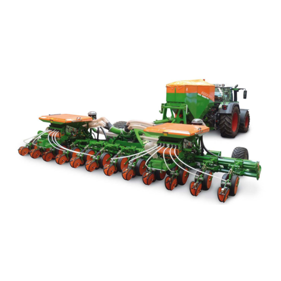
Summary of Contents for Amazone EDX 9000-TC
- Page 1 Operating manual Precision airplanter EDX 9000-TC Please read this operating manual before initial operation. MG4346 Keep it in a safe place for BAH0048-6 09.2019 future use!
- Page 2 Only by doing so would you be satisfied both with the machine and also with yourself. To achieve this is the purpose of this instruction manual. Leipzig-Plagwitz 1872. EDX 9000-TC BAH0048-6 09.2019...
- Page 3 + 49 (0) 5405 501-234 E-mail: amazone@amazone.de Spare part orders Spare parts lists are freely accessible in the spare parts portal at www.amazone.de. Please send orders to your AMAZONE dealer. Formalities of the operating manual Document number: MG4346 Compilation date: 09.2019 ...
- Page 4 Send us your suggestions by fax. AMAZONEN-WERKE H. DREYER GmbH & Co. KG Postfach 51 D-49202 Hasbergen, Germany Tel.: + 49 (0) 5405 50 1-0 Fax: + 49 (0) 5405 501-234 E-mail: amazone@amazone.de EDX 9000-TC BAH0048-6 09.2019...
-
Page 5: Table Of Contents
Proper use ..........................57 Danger areas and danger points ................... 58 Rating plate and CE mark ...................... 59 4.10 Technical data ........................60 4.11 Necessary tractor equipment ....................61 EDX 9000-TC BAH0048-6 09.2019... - Page 6 Checking the suitability of the tractor .................. 100 6.1.1 Calculating the actual values for the total tractor weight, tractor axle loads and load capacities, as well as the minimum ballast ................. 101 EDX 9000-TC BAH0048-6 09.2019...
- Page 7 Adjusting the implement wheel mark eradicator ..............153 Adjusting the tractor wheel mark eradicator ................ 154 Adjusting the pre-emergence marker .................. 155 Adjusting fan speed ......................156 EDX 9000-TC BAH0048-6 09.2019...
- Page 8 12.5.5 Checking the fertiliser coulter's coulter disc ................ 219 12.5.6 Checking the fertiliser coulter furrow former ............... 220 12.5.7 Checking the wear bushing on the support roller arm ............220 EDX 9000-TC BAH0048-6 09.2019...
- Page 9 Hydro-pneumatic pressure reservoir (specialist workshop) ..........240 12.10 Bolt tightening torques ......................241 Hydraulic diagram ..................242 13.1 Hydraulic diagram for EDX 9000-TC ................... 242 Notes ......................245 EDX 9000-TC BAH0048-6 09.2019...
-
Page 10: User Information
Item numbers in illustrations Numbers in round brackets refer to the item numbers in the illustrations. The first number refers to the figure and the second number to the item. Example: (Fig. 3/6) Figure 3 Item 6 EDX 9000-TC BAH0048-6 09.2019... -
Page 11: General Safety Instructions
If the user discovers that a function is not working properly, then they must eliminate this fault immediately. If this is not the task of the user or if the user does not possess the appropriate technical knowledge, then they should report this fault to their superior (operator). EDX 9000-TC BAH0048-6 09.2019... - Page 12 Unauthorised design changes to the implement Insufficient monitoring of implement parts which are subject to wear Improperly executed repairs Disasters due to the effects of foreign objects and force majeure. EDX 9000-TC BAH0048-6 09.2019...
-
Page 13: Presentation Of Safety Symbols
Non-compliance with these instructions can cause faults on the implement or disturbance to the environment. NOTE Indicates handling tips and particularly useful information. These instructions will help you to use all the functions of your implement in the best way possible. EDX 9000-TC BAH0048-6 09.2019... -
Page 14: Organisational Measures
As well as all the safety information in this operating manual, comply with the general, national regulations pertaining to accident prevention and environmental protection. When driving on public roads and routes you should comply with the statutory road traffic regulations. EDX 9000-TC BAH0048-6 09.2019... -
Page 15: User Training
"Specialist workshop". The personnel of a specialist workshop shall possess the appropriate knowledge and suitable aids (tools, lifting and support equipment) for carrying out the maintenance and repair work on the implement in a way which is both appropriate and safe. EDX 9000-TC BAH0048-6 09.2019... -
Page 16: Safety Measures In Normal Operation
Carefully fix and secure larger assembly groups to lifting gear when carrying out replacement work. Check all the bolted connections for tightness. On completion of the maintenance work, check the function of the safety devices. EDX 9000-TC BAH0048-6 09.2019... -
Page 17: Design Changes
Immediately replace any implement parts which are not in a perfect state. Use only genuine AMAZONE spare and wear parts or the parts cleared by AMAZONEN-WERKE so that the operating permit retains its validity in accordance with national and international regulations. If... -
Page 18: Cleaning And Disposal
when cleaning using solvents. 2.12 Workstation of the operator The implement may be operated by only one person sitting in the driver's seat of the tractor. EDX 9000-TC BAH0048-6 09.2019... -
Page 19: Warning Symbols And Other Markings On The Machine
2. The consequence of non-compliance with the risk avoidance instructions. For example: causes serious injuries to fingers or hands. 3. The risk avoidance instructions. For example: only touch implement parts when they have come to a complete standstill. EDX 9000-TC BAH0048-6 09.2019... - Page 20 It is forbidden to ride on the implement or climb the implement when it is running. This prohibition also applies to implements with step surfaces or platforms. Make sure that nobody is riding on the implement. EDX 9000-TC BAH0048-6 09.2019...
- Page 21 Maintain an adequate safety distance from any suspended loads or raised implement parts. Ensure that all personnel maintain an adequate safety distance from suspended loads or raised implement parts. EDX 9000-TC BAH0048-6 09.2019...
- Page 22 Read and observe the information in the operating manual before carrying out maintenance work on the hydraulic hose lines. If you are injured by hydraulic fluid, contact a doctor immediately. EDX 9000-TC BAH0048-6 09.2019...
- Page 23 Secure the tractor and the implement against unintentional start-up and rolling before any intervention in the implement. Depending on the type of intervention, read and understand the information in the relevant sections of the operating manual. EDX 9000-TC BAH0048-6 09.2019...
- Page 24 Will cause serious injuries anywhere on the body or death. Secure the implement against moving away unintentionally before uncoupling the implement from the tractor. To do this, use the parking brake and/or the wheel chock(s). EDX 9000-TC BAH0048-6 09.2019...
- Page 25 Instruct people to leave the danger area between the tractor and the implement whenever the engine of the tractor is running and the tractor is not secured against unintentional rolling. EDX 9000-TC BAH0048-6 09.2019...
-
Page 26: Position Of The Warning Signs And Other Markings
General Safety Instructions 2.13.1 Position of the warning signs and other markings Warning signs The following diagrams show the arrangement of the warning symbols on the implement. Fig. 1 Fig. 2 EDX 9000-TC BAH0048-6 09.2019... - Page 27 General Safety Instructions Fig. 3 Fig. 4 EDX 9000-TC BAH0048-6 09.2019...
-
Page 28: Dangers In Case Of Non-Observance Of The Safety Instructions
Comply with the accident prevention instructions on the warning symbols. When driving on public roads and routes, comply with the appropriate statutory road traffic regulations. EDX 9000-TC BAH0048-6 09.2019... -
Page 29: Safety Information For Users
Drive in such a way that you always have full control over the tractor with the attached implement. In so doing, take your personal abilities into account, as well as the road, traffic, visibility and weather conditions, the driving characteristics of the tractor and the connected or coupled implement. EDX 9000-TC BAH0048-6 09.2019... - Page 30 must not chafe against other parts. The release ropes for quick action couplings must hang loosely and may not release themselves when lowered. Also ensure that uncoupled implements are stable! EDX 9000-TC BAH0048-6 09.2019...
- Page 31 Secure the tractor against unintentional start-up and rolling, before you leave the tractor. For this: Lower the implement onto the ground. apply the tractor parking brake switch off the tractor engine remove the ignition spanner. EDX 9000-TC BAH0048-6 09.2019...
- Page 32 Before driving downhill, switch to a low gear. Before road transport, always switch off the independent wheel braking (lock the pedals). Observe the maximum permissible total weight. Only transport the implement with empty seed and fertiliser hoppers. EDX 9000-TC BAH0048-6 09.2019...
-
Page 33: Attached Implements
Only a specialist workshop may adjust the height of the drawbar on straight draw bars with a drawbar load. EDX 9000-TC BAH0048-6 09.2019... -
Page 34: Hydraulic System
Replace the hydraulic hose lines if they are damaged or worn. Only use original AMAZONE hydraulic hose lines. The hydraulic hose lines should not be used for longer than six years, including any storage time of maximum two years. Even... -
Page 35: Electrical System
Ensure that the retrofitted electrical and electronic components comply with the EMC directive 2004/108/EEC in the appropriate version and carry the CE mark. EDX 9000-TC BAH0048-6 09.2019... -
Page 36: Brake System
Replace the air reservoir if: The air reservoir can be moved in the tensioning belts. The air reservoir is damaged. The rating plate on the air reservoir is rusty, loose or missing. EDX 9000-TC BAH0048-6 09.2019... -
Page 37: Tyre
After the PTO shaft is switched off, there is a risk of injury from the continued rotation of freewheeling implement parts. Do not approach too near to the implement during this time. You must only start work on the implement once all implement parts are at a complete standstill. EDX 9000-TC BAH0048-6 09.2019... -
Page 38: Operation Of The Precision Airplanter
Spare parts must meet at least the specified technical requirements of AMAZONEN-WERKE! This is ensured through the use of original AMAZONE spare parts. EDX 9000-TC BAH0048-6 09.2019... -
Page 39: Loading And Unloading
When lifting the implement sections out of the transport locking mechanism (Fig. 6/1), the lighting is folded down. When unfolding the sections, wait until the lighting is completely folded down (see also section "Unfolding implement sections") to prevent collisions. Fig. 6 EDX 9000-TC BAH0048-6 09.2019... -
Page 40: Removal Of Individual Implement Components In Order To Comply With The Permitted Transport Height
2. Remove the loading boards (Fig. 8/1). 2.1 Each loading board is attached with 4 bolts (Fig. 8/2). Fig. 8 In transport position, after dismounting the components: Transport height: 3.7 m Transport width: 3.0 m EDX 9000-TC BAH0048-6 09.2019... -
Page 41: Fastening The Seed Tube Hoses
(from Fuchs) before fastening the union nut. Only tighten the union nut by hand to prevent damage. The opto-sensor wrench (Fig. 10) serves to loosen and fasten the union nuts, especially for narrow-row seed drills. Fig. 10 EDX 9000-TC BAH0048-6 09.2019... -
Page 42: Loading And Unloading With A Tractor
Pneumatic braking system: Only move off with the implement connected when the pressure gauge on the tractor shows 5.0 bar! WARNING A marshalling person is required for the loading and unloading. EDX 9000-TC BAH0048-6 09.2019... -
Page 43: Loading The Attached Implement
Bear in mind that the implement may have no parking brake. 6. Uncouple the tractor from the implement. Fig. 12 The symbol marks the lashing points on the implement. 7. Uncouple the tractor from the implement. Fig. 13 EDX 9000-TC BAH0048-6 09.2019... -
Page 44: Unloading The Attached Implement
5. Fold out the implement, see "Important information", Seite 39. 6. Fit the loading boards (Fig. 8). 7. Fit the seed tubes (see "Fastening the seed tube hoses", Seite 41). 8. Disconnect the implement from the tractor (see section 7.5, Seite 125). EDX 9000-TC BAH0048-6 09.2019... -
Page 45: Product Description
(4) Fertiliser distributor head (10) Support wheel (5) Seed hopper (11) Track marker (6) Exhaust air hose (12) Star wheel (7) Seed line hoses (13) PTO shaft driven hydraulic pump for the fan drive (fertiliser) EDX 9000-TC BAH0048-6 09.2019... - Page 46 Fig. 15 Fig. 16/... (1) Tensioned crosspiece (2) Jack, extendable Fig. 16 Fig. 17/... (1) Mounting for supply lines Fig. 17 Fig. 18/... (1) Fill level sensor (seed) (2) Sensor (compressed air) Fig. 18 EDX 9000-TC BAH0048-6 09.2019...
- Page 47 Fig. 19 Fig. 20/... (1) Setting lever for the air deflector Fig. 20 Fig. 21/... sealing lip Setting lever for the Fig. 21 Fig. 22/... (1) Setting lever for the mech. adjustable seed scraper Fig. 22 EDX 9000-TC BAH0048-6 09.2019...
- Page 48 Fig. 25/... (1) Ladder (2) Loading board (3) Holding point Fig. 25 Fig. 26/... (1) Fill level sensor (fertiliser) Please note: the charging sieve, which is folded up for clarification, remains closed while making settings. Fig. 26 EDX 9000-TC BAH0048-6 09.2019...
- Page 49 (2) Vario gearbox (see also Fig. 31) (3) Metering unit (see also Fig. 30) Fig. 29 Fig. 30/... (1) Calibration crank (in transport bracket) (2) Metering unit with integrated fertiliser metering roller (3) Injector sluice Fig. 30 EDX 9000-TC BAH0048-6 09.2019...
- Page 50 (2) Electrohydraulic control block 2 Fig. 33 Functions: Pressure of the double disc coulter Pressure of the fertiliser coulter Pressure / folding of the implement sections Automatically running functions: Height adjustment of the seed hopper EDX 9000-TC BAH0048-6 09.2019...
-
Page 51: Electronic Monitoring And Operation (Optional)
Observe the corresponding operating manual when using the implement with the control terminal! AMATRON 3 Fig. 34/.: monitored function ISOBUS implement control Fig. 34 Control options for ISOBUS control terminal Fig. 35/.: 1. AMASTICK 2. AMAPILOT Fig. 35 EDX 9000-TC BAH0048-6 09.2019... -
Page 52: Camera System (Option)
Fig. 36 Safety and protective equipment Fig. 37/… (1) Charging sieve (acts as guard screen in fertiliser hopper) Fig. 37 Fig. 38/… (1) Locking hooks (for locking the implement sections during transport) Fig. 38 EDX 9000-TC BAH0048-6 09.2019... - Page 53 (1) Stop for the implement sections (Prevents collisions of the implement sections with the fertiliser hopper) (2) Adjustment screw for the stop (4 pcs. / implement) Fig. 39 Fig. 40/… (1) Wheel chocks (parking position under the seed hopper) Fig. 40 EDX 9000-TC BAH0048-6 09.2019...
-
Page 54: Supply Lines Between The Tractor And The Implement
(1) Dual-circuit pneumatic braking system: brake / supply line (2) Hydraulic hose lines (3) Implement plug for on-board computer, implement lighting (7-pin) Without illustration: Hydraulic brake line (not approved for Germany and some other EU countries) Fig. 41 EDX 9000-TC BAH0048-6 09.2019... - Page 55 Implement plug (see section 5.2, Seite 66) AMATRON 3 on-board computer Connector (7-pin) Road traffic lighting system Hydraulic brake line (see section 7.2, Seite 115) Hydraulic service brake system not allowed in Germany and in many other EU countries EDX 9000-TC BAH0048-6 09.2019...
-
Page 56: Transportation Equipment
(1) 2 x 3 reflectors, yellow, (laterally with a max. spacing of 3 m) Supplemental for identification according to GostR (optional, not shown) 2 reflectors facing the front, white 2 reflectors facing the rear, red Fig. 44 EDX 9000-TC BAH0048-6 09.2019... -
Page 57: Proper Use
adherence of inspection and maintenance work Exclusive use of original AMAZONE spare parts. Other uses to those specified above are forbidden and shall be considered as improper. For any damage resulting from improper use ... -
Page 58: Danger Areas And Danger Points
by climbing onto the implement. behind the implement in the area of the seed hopper. If the seed hose is torn off, seed shoots out of the optical sensor. EDX 9000-TC BAH0048-6 09.2019... -
Page 59: Rating Plate And Ce Mark
Perm. drawbar load kg Perm. rear axle load kg Perm. system pressure bar Perm. total weight kg Factory Fig. 45 Model year Year of construction (beside the CE mark) EDX 9000-TC BAH0048-6 09.2019... -
Page 60: Technical Data
Operation without a brake system is not permitted in Germany and in some other countries. Operation with a hydraulic brake system is not permitted in Germany and in several other countries. Number of Row spacing [cm] Working width Machine type seeding units EDX 9000-TC Fig. 46 EDX 9000-TC BAH0048-6 09.2019... -
Page 61: Necessary Tractor Equipment
Up to 16 rows, starting at 184 kW (250 HP) Above 18 rows, starting at 221 kW (300 HP) Electrical system Required output of tractor alternator with EDX 9000-TC: 12V at 150 A Lighting socket: 7-pin EDX 9000-TC BAH0048-6 09.2019... -
Page 62: Noise Production Data
The workplace-related emission value (acoustic pressure level) is 70 dB(A), measured in operating condition at the ear of the tractor driver with the cab closed. Measuring unit: OPTAC SLM 5. The noise level is primarily dependent on the vehicle used. EDX 9000-TC BAH0048-6 09.2019... -
Page 63: Structure And Function
The next bout on the field is marked by the track markers (Fig. 47/8), e.g. for 75 cm row spacing, at the centre of the tractor. The implement can be folded to a transport width of 3 m. EDX 9000-TC BAH0048-6 09.2019... -
Page 64: Service Brake System
Check the suitability of the tractor for operation without service brake system (see section 6.1.3). Fig. 48 5.1.2 Immobiliser Lockable device for the drawbar eye, ball bracket, or lower link crosspiece, prevents unauthorised use of the machine. Fig. 49 EDX 9000-TC BAH0048-6 09.2019... -
Page 65: Parking Brake
Implements without their own brake system The implement may be equipped without a service brake system. The implement is not approved for Germany, the EU countries and several other countries without its own brake system (see section 6.1.3, page 105). EDX 9000-TC BAH0048-6 09.2019... -
Page 66: Amatron 3 Control Terminal
For a commenced task, the AMATRON 3 stores the daily and total volume of seed/fertiliser applied [kg] the day and total area cultivated [ha] the day and total seeding time [h] the average work performance [ha/h] EDX 9000-TC BAH0048-6 09.2019... -
Page 67: Controlling The Implement With The Amatron 3 On-Board Computer
(hectare counter). The "working position" sensor transmits the star wheel position to the on-board computer. When the star wheel is lowered, the on-board computer activates the functions that are required during operation. Fig. 53 EDX 9000-TC BAH0048-6 09.2019... -
Page 68: Frame And Implement Sections
is positioned more or less vertically before the implement sections are retracted (Fig. 54/3). two implement sections which are retractable for transportation purposes (Fig. 54/3). EDX 9000-TC BAH0048-6 09.2019... -
Page 69: Seed Singling And Spreading
The modular separation of the singling unit and seeding operations makes reliable seed placement possible, even at high working speeds up to 15 km/h. Before folding the implement sections into transport position, the unit is lowered into transport position. EDX 9000-TC BAH0048-6 09.2019... -
Page 70: Single Row Control (Optional)
Table (Fig. 60) and installed (see section "Removing/installing the singling drum", Seite 207). The singling drums differ in the number of rows (Fig. 59/1) and in the hole diameters. Fig. 59 EDX 9000-TC BAH0048-6 09.2019... - Page 71 8 km/h 9 km/h 600,000 500,000 400,000 380,000 300,000 250,000 200,000 50 cm K/ha K/ha K/ha K/ha K/ha K/ha K/ha 700,000 580,000 480,000 400,000 310,000 310,000 220,000 45 cm K/ha K/ha K/ha K/ha K/ha K/ha K/ha EDX 9000-TC BAH0048-6 09.2019...
-
Page 72: Seed Shutter
The air quantity is correctly metered when the seed grains move loosely at the viewing window (without jumping). are not thrown across the singling drum. Fig. 63 EDX 9000-TC BAH0048-6 09.2019... -
Page 73: Seed Scraper
If at working speed, the AMATRON 3 indicates gaps or doubles, correct the scraper position as described in the AMATRON 3 operating manual. Fig. 65 An electrical setting motor (Fig. 66/1), controlled by the AMATRON 3, adjusts the seed scraper. Fig. 66 EDX 9000-TC BAH0048-6 09.2019... -
Page 74: Digital Seed Fill Level Monitoring
This alarm is intended to remind the tractor driver to refill the hopper in due time. Fig. 67 The fill level sensor with the cable output must be inserted flush in the holder (Fig. 68/1). Fig. 68 EDX 9000-TC BAH0048-6 09.2019... -
Page 75: Fine Seed (Optional)
Fig. 69/… (1) Singling drum ( 1.2 / 1.6) (2) Fluid bed shutter (very fine mesh) Fig. 69 Fig. 70/… (1) Sealing brushes Fig. 70 Fig. 71/… (1) Press roller scraper, adjustable Fig. 71 EDX 9000-TC BAH0048-6 09.2019... -
Page 76: Baffle Plate (Optional)
(pressure tank). The AMATRON 3 issues an alarm if holes in the singling drum are not occupied by seed grains. The alarm is triggered if no seed is detected by Fig. 74 the opto-sensors. EDX 9000-TC BAH0048-6 09.2019... -
Page 77: Blower Fan Hydraulic Motor With Connection To The Tractor Hydraulic System
Set the fan speed according to section 8.7.2. The hydraulic pump (Fig. 76/1) is driven by the tractor PTO shaft. Fig. 76 In a closed circuit, the implement carries the hydraulic fluid in an oil tank (Fig. 77/1). Fig. 77 EDX 9000-TC BAH0048-6 09.2019... -
Page 78: Double Disc Coulter
Check the placement depth and grain spacing Following every adjustment to the seed placement depth When changing from light to heavy soil and vice-versa. The carrier rollers penetrate the ground more deeply with light soil than with heavy soil. EDX 9000-TC BAH0048-6 09.2019... -
Page 79: Coulter Pressure (Double Disc Coulter)
(Fig. 83/1) or on the AMATRON 3 display (with the optional "setting motor"). Actuation of the electr. coulter pressure adjustment is described in the AMATRON 3 operating manual. Fig. 83 EDX 9000-TC BAH0048-6 09.2019... -
Page 80: Applying Pressure On The Unfolded Sections
(Fig. 84/1) or from the tractor seat on the pressure gauge (Fig. 85/1). Fig. 85 The pressure displayed on the pressure gauge (Fig. 84/1) changes until the fan (singling) runs at a constant speed. EDX 9000-TC BAH0048-6 09.2019... -
Page 81: Ground Contact Pressure And Intensity Of Press Rollers
(Fig. 87/1). Adjust the position of the press rollers to the ground or the seed furrow. Fig. 87 If the desired results are not obtained, adjust the press rollers by turning the axle. The lever (Fig. 88/1) serves for adjustment. Fig. 88 EDX 9000-TC BAH0048-6 09.2019... -
Page 82: Star Clearer (Optional)
The star clearers are adjustable and suitable for mulch seeding. Fig. 89 5.6.6 Clod clearer (optional) The clod clearers (Fig. 90/1) level out the seed furrow track. The clod clearers are adjustable and suitable for mulch seeding. Fig. 90 EDX 9000-TC BAH0048-6 09.2019... -
Page 83: Carrier Roller Scraper (Optional)
45 cm. The scrapers (Fig. 91/2) are adjustable. Fig. 91 5.6.8 Press roller scraper (only for fine seeds) Seeding coulters with a 12 mm feed channel have an adjustable scraper on the press roller. Fig. 92 EDX 9000-TC BAH0048-6 09.2019... -
Page 84: Fertiliser Metering And Application
The cover hook (Fig. 94/3) serves to release or hook on the rubber loops. The full-area opening of the hopper allows rapid filling. Fig. 94 In parking position, the cover hook (Fig. 95/1) is inserted in the bracket under the hopper. Fig. 95 EDX 9000-TC BAH0048-6 09.2019... -
Page 85: Digital Fertiliser Fill Level Monitoring (Optional)
Fig. 96 level sensor. Increase the residual fertiliser volume that triggers the alarm the higher the spread rate, the greater the working width. The fill level sensor may not rest against the hopper wall! EDX 9000-TC BAH0048-6 09.2019... -
Page 86: Filling Auger (Optional)
EDX. Fig. 97 Folded-in condition of the filling auger for transport and use. Fig. 98 Fig. 101/… 1. Folding and unfolding 2. Switch on the filling auger Fig. 99 EDX 9000-TC BAH0048-6 09.2019... -
Page 87: Fertiliser Metering Unit And Injector Sluice
(Fig. 195) and is conveyed by the air current to the distributor head and then to the fertiliser coulters. For calibration testing and emptying purposes, the fertiliser falls through an opening in the floor of the injector sluice. Fig. 101 EDX 9000-TC BAH0048-6 09.2019... -
Page 88: Fertiliser Quantity Adjustment On The Vario Gearbox
An outer white scale (Fig. 103/1) for fertiliser quantities above 30 kg/ha An inner white scale (Fig. 103/2) for fertiliser quantities below 30 kg/ha A coloured scale (Fig. 103/3) with all gearbox settings from 1 to 100. Fig. 103 EDX 9000-TC BAH0048-6 09.2019... -
Page 89: Calibration Test
The calibration troughs secured to the hopper rear wall using a linch pin (Fig. 104/1) for transport. Fig. 104 The calibration crank (Fig. 105/1) is in parking position in the transport bracket. Fig. 105 EDX 9000-TC BAH0048-6 09.2019... -
Page 90: Blower Fan Speed For Transporting The Fertiliser
Fig. 107 5.7.6 Distributor head The fertiliser is distributed evenly amongst all fertiliser coulters in the distributor head (Fig. 108/1). One fertiliser metering unit always supplies one distributor head. Fig. 108 EDX 9000-TC BAH0048-6 09.2019... -
Page 91: Single Disc Type Fertiliser Coulter
Fig. 110 Read the pressure that is being applied to the central adjustment on the pressure gauge (Fig. 110/1), Fig. 111 from the tractor seat on the pressure gauge (Fig. 112/1). Fig. 112 EDX 9000-TC BAH0048-6 09.2019... - Page 92 The distance between the fertiliser and seed placement can be adjusted. (Specialist workshop). Only very light soils, the single-disc fertiliser coulter can be guided by the seeding coulter down into the soil using a adjustable chain (optional, Fig. 113/1). Fig. 113 EDX 9000-TC BAH0048-6 09.2019...
-
Page 93: One Sided Shut-Off (Part-Width Section)
Structure and function 5.7.8 One sided shut-off (part-width section) The EDX 9000-TC precision airplanter can be operated with half the working width (part-width section). One-sided seed shut-off The seed supply can be switched off on one side by switching off the electric motor of one of the singling drums. -
Page 94: Track Marker
Changing the row spacing can require changing of the track marker. Before folding the implement sections for road transport, the track markers (Fig. 117/1) rest closely on the implement sections. Fig. 117 EDX 9000-TC BAH0048-6 09.2019... -
Page 95: Support Wheels
Fig. 119 5.10 Running gear with twin tyres (optional) To avoid compaction in the seedbed, a running gear with twin tyres can be used for selected row spacings. Fig. 120 EDX 9000-TC BAH0048-6 09.2019... -
Page 96: Implement Wheel Track Eradicator (Optional)
When lifting the implement at the headlands or for road transport, the tractor wheel mark eradicators must be swivelled up by approx. 90°. Throwing over the lever (Fig. 123/1) allows work to be performed without the tractor wheel mark eradicators. Fig. 123 EDX 9000-TC BAH0048-6 09.2019... -
Page 97: Pre-Emergence Marker (Option)
The following are adjustable the track width of the tramline, the working intensity of the track discs. The track discs are raised if no tramline is created. Fig. 124 EDX 9000-TC BAH0048-6 09.2019... -
Page 98: Lighting Of The Work Tools (Optional)
The switch (Fig. 127) for the lighting can be fastened to the implement or in the tractor cab. Connect the plug for the lighting to the 12 Volt power socket in the tractor cab. Fig. 127 EDX 9000-TC BAH0048-6 09.2019... -
Page 99: Start-Up
This does not apply to equipment movements that: are continuous or are automatically locked or require a float position or pressure position due to their function. EDX 9000-TC BAH0048-6 09.2019... -
Page 100: Checking The Suitability Of The Tractor
The front axle of the tractor must always be subjected to at least 20 % of the tare weight of the tractor. The tractor must achieve the brake delay specified by the tractor manufacturer, even with the implement connected. EDX 9000-TC BAH0048-6 09.2019... -
Page 101: Calculating The Actual Values For The Total Tractor Weight, Tractor Axle Loads And Load Capacities, As Well As The Minimum Ballast
§ 70 of the German Regulations Authorising the Use of Vehicles for Road Traffic and the required approval according to § 29, paragraph 3 of the German Road Traffic Regulations. EDX 9000-TC BAH0048-6 09.2019... -
Page 102: Data Required For The Calculation (Hitched Implement)
[m] Tractor wheel base See tractor operating manual or vehicle documents or measurement [m] Distance between the centre of the rear See tractor operating manual or vehicle axle and the centre of the lower link documents or measurement connection EDX 9000-TC BAH0048-6 09.2019... -
Page 103: Calculation Of The Required Minimum Ballasting At The Front G
(section 6.1.1.7). 6.1.1.6 Tyre load capacity Enter the double value (two tyres) of the approved load capacity (see, for example, tyre manufacturer's documentation) in the table (section 6.1.1.7). EDX 9000-TC BAH0048-6 09.2019... -
Page 104: Table
(if required) attached to the tractor for the minimum front ballast (G V min You must use a front weight, which is equal to at least the required minimum front ballast (G V min EDX 9000-TC BAH0048-6 09.2019... -
Page 105: Requirements For Tractor Operation With Attached Implements
The maximum forward speed is 25 km/h. Note: in Russia and in several other countries, the permissible maximum speed is 10 km/h. Some countries may have different regulations. EDX 9000-TC BAH0048-6 09.2019... -
Page 106: Securing The Tractor/Implement Against Unintentional Start-Up And Rolling
This is how to prevent unintentional falling: 3. Shut down the tractor engine. 4. Remove the ignition key. 5. Apply the tractor parking brake. 6. Secure the implement with wheel chocks against unintentionally rolling away. EDX 9000-TC BAH0048-6 09.2019... -
Page 107: Installation Regulations For The Hydraulic Fan Drive Connection (Singling Unit)
The capacity of the tractor's oil tank (Fig. 129/4) should be at least twice the oil flow rate. If the hydraulic fluid heats up excessively, the installation of an oil cooler is required at a specialist workshop. EDX 9000-TC BAH0048-6 09.2019... -
Page 108: Coupling And Uncoupling The Implement
With the implement extended, lower the rear frame or coulter completely before uncoupling the implement from the tractor. When the coulters are raised, the tensioned crosspiece may move rapidly upwards when the tractor's lower link is released. EDX 9000-TC BAH0048-6 09.2019... -
Page 109: Dual-Circuit Pneumatic Service Brake System
(red) is connected. Only then can the wheel chocks be removed. Compliance with the maintenance intervals is essential for the correct function of the brake system. EDX 9000-TC BAH0048-6 09.2019... - Page 110 The brake is not released if the implement's parking brake is applied. To make sure that the implement is braked after uncoupling, apply the implement's parking brake beforehand. Only release the parking brake once the implement has been coupled up to the tractor. EDX 9000-TC BAH0048-6 09.2019...
-
Page 111: Coupling The Brake And Supply Lines
Check the routing of the brake line. The brake line must not chafe on other parts. 1. Check if the implement is secured with 2 wheel chocks and the implement parking brake is applied. Fig. 132 EDX 9000-TC BAH0048-6 09.2019... - Page 112 In an emergency, pull the red button (Fig. 134/1) to brake the implement. The implement does not have any braking effect if the tractor parking brake is released when the supply line (red) is connected. Fig. 134 EDX 9000-TC BAH0048-6 09.2019...
-
Page 113: Uncoupling The Supply And Brake Line
(red). Fig. 135 3. Release the coupling head of the brake line (yellow). 4. Fasten the coupling heads in the empty couplings. 5. Close the covers of the coupling heads on the tractor. Fig. 136 EDX 9000-TC BAH0048-6 09.2019... -
Page 114: Control Elements Of The Dual-Circuit Pneumatic Service Brake System
When the supply line (red) is coupled to the tractor, the parking brake is released automatically, and as soon as the operating pressure has built up, the black button (Fig. 137/1) will be automatically pulled out of the valve chest. EDX 9000-TC BAH0048-6 09.2019... -
Page 115: Hydraulic Service Brake System
Engage the parking brake before uncoupling the implement and do not disengage it until after coupling the implement to the tractor. Compliance with the maintenance intervals is essential for the correct function of the brake system. EDX 9000-TC BAH0048-6 09.2019... -
Page 116: Coupling The Hydraulic Service Brake System
5. Couple the hydraulic socket to the tractor. Fig. 138 6. Connect the break-away valve to the tractor using the cable (Fig. 139/1). If the implement is separated from the tractor due to an accident, the implement will be braked. Fig. 139 EDX 9000-TC BAH0048-6 09.2019... - Page 117 into the hose line to the tractor and impedes the coupling of the brake line to the tractor. In these cases, relieve pressure using the hand pump on the brake valve. EDX 9000-TC BAH0048-6 09.2019...
-
Page 118: Uncoupling The Hydraulic Service Brake System
4. Apply the parking brake. 5. Uncouple the hydraulic socket from the tractor. 6. Protect the hydraulic socket and the hydraulic connector against soiling using protective caps (Fig. 143/1). 7. Place the hydraulic lines in the hose cabinet. Fig. 143 EDX 9000-TC BAH0048-6 09.2019... -
Page 119: Hydraulic Hose Lines
(neutral position). 2. Clean the hydraulic connectors of the hydraulic hose lines before you couple the hydraulic hose lines to the tractor. 3. Connect the hydraulic hose line(s) to the tractor control unit(s). Fig. 144 EDX 9000-TC BAH0048-6 09.2019... -
Page 120: Uncoupling The Hydraulic Hose Lines
During coupling, check the course of the power lines. The supply lines must give slightly without tension, bending or rubbing on all movements of the connected implement. must not chafe against other parts. EDX 9000-TC BAH0048-6 09.2019... - Page 121 Do not remove the wheel chocks until the implement is connected to the tractor's lower links and the tractor parking brake is applied. 1. Verify that the implement is secured with wheel chocks (Fig. 145/1). 2. Apply the implement's parking brake. Fig. 145 EDX 9000-TC BAH0048-6 09.2019...
- Page 122 Connect the implement plugs to the terminal as described in the AMATRON 3 operating manual. Clean the hydraulic couplings before connecting them to the tractor. Minor oil contamination with particles can cause a failure of the hydraulic system. EDX 9000-TC BAH0048-6 09.2019...
- Page 123 15. Hold the jack tightly by the handle (Fig. 147/1) and remove the positioning pin (Fig. 147/2). 16. Push up the jack and secure it using the positioning pin (Fig. 147/1). 17. Secure the positioning pin with the supplied linch pin. Fig. 147 EDX 9000-TC BAH0048-6 09.2019...
- Page 124 Fig. 149 Check the route of the supply lines. The supply lines must easily give way to all movements in bends without tensioning, kinking or rubbing. must not chafe against other parts. EDX 9000-TC BAH0048-6 09.2019...
-
Page 125: Uncoupling The Implement
3. Fold the implement completely in or out. 4. Switch off the AMATRON 3. 4.1 Press the (Fig. 150/1) button. 5. Apply the tractor parking brake, switch the tractor engine off and remove the ignition spanner. Fig. 150 EDX 9000-TC BAH0048-6 09.2019... - Page 126 the coupling of the hydraulic service brake system. When uncoupling the dual-circuit pneumatic service braking system, first disconnect the red hose coupling (supply line) and then the yellow hose coupling (brake line) from the tractor! EDX 9000-TC BAH0048-6 09.2019...
- Page 127 19. Pull the tractor forwards. DANGER While pulling the tractor forwards no personnel are allowed to be between the tractor and the implement! Fig. 156 CAUTION Danger of getting crushed in the area of the moving tensioned crosspiece. EDX 9000-TC BAH0048-6 09.2019...
-
Page 128: Aligning A Towed Implement
1. Spread seed for approx. 100 m at working speed on the field. 2. Adjust the tractor lower link such that the horizontal spirit level (Fig. 159/1) on the coulter frame indicates a horizontal position. Fig. 159 EDX 9000-TC BAH0048-6 09.2019... -
Page 129: Coupling The Hydraulic Pump
PTO shaft. The hydraulic pump is equipped with a QC fastener. Make sure that the QC fastener Fig. 160 has engaged correctly. 6. Set the adjuster segment so that both buffers (Fig. 160/2) rest against it. EDX 9000-TC BAH0048-6 09.2019... -
Page 130: Uncoupling The Hydraulic Pump
4. Uncouple the hydraulic pump (Fig. 162/1) from the tractor's PTO shaft. The hydraulic pump is equipped with a QC fastener. Fig. 162 5. Insert the hydraulic pump (Fig. 163/1) on the transport bracket. Fig. 163 EDX 9000-TC BAH0048-6 09.2019... -
Page 131: Settings
unintentional start-up and rolling of the tractor-implement combination. Secure the tractor and the implement against unintentional starting and rolling away before you make any adjustments to the implement. EDX 9000-TC BAH0048-6 09.2019... -
Page 132: Seed Metering And Application
(-). Sunflower / Sorghum contains too little seed: Fig. 166 Move the lever (Fig. 165/1) counterclockwise (+). If the lever points to the scale value "0", the inlet from the seed hopper is closed. EDX 9000-TC BAH0048-6 09.2019... -
Page 133: Adjusting The Air Guide
169). The table values (Fig. 169 to ) are reference values. For example, small free- flowing maize grains require less air than large maize grains with a sticky dressing. Check the results of the adjustment in the viewing window (Fig. 47/3). Fig. 168 EDX 9000-TC BAH0048-6 09.2019... - Page 134 This setting influences the occupancy of the seed grains in the holes of the singling drum. Multiple occupancy and gaps in the holes of the singling drum are detected by the opto-sensors after working speed has been reached. The AMATRON 3 issues an alarm. EDX 9000-TC BAH0048-6 09.2019...
-
Page 135: Setting The Seed Scraper
Adjust the indicator (Fig. 173/1) of the seed scraper on the AMATRON 3. Take the preliminary setting value from Table (Fig. 171). For a more detailed description, refer to the AMATRON 3 operating manual. Fig. 173 EDX 9000-TC BAH0048-6 09.2019... -
Page 136: Adjusting The Seed Placement Depth
Check the placement depth and grain spacing Following every adjustment to the seed placement depth When changing from light to heavy soil and vice-versa. The carrier rollers penetrate the ground more deeply with light soil than with heavy soil. EDX 9000-TC BAH0048-6 09.2019... -
Page 137: Setting The Coulter Pressure
Seite 154). The pressure displayed on the pressure gauge (Fig. 176/1) changes until the fan (singling) runs at a constant speed. Check the setting (see section "Checking the placement depth and grain spacing", Seite 142). EDX 9000-TC BAH0048-6 09.2019... -
Page 138: Setting The Sections Pressure
3. Tighten the lock nut. Fig. 177 The pressure displayed on the pressure gauge (Fig. 177/1) changes until the fan (singling) runs at a constant speed. Check the setting (see section "Checking the placement depth and grain spacing", Seite 142). EDX 9000-TC BAH0048-6 09.2019... -
Page 139: Adjusting The Ground Contact Pressure And Intensity Of The Press Rollers
6. Rotate the axle by moving the lever (Fig. 180/1). 7. Secure the lever position with the bolt (Fig. Fig. 179 180/2). 8. Make the same settings on all seeding units. Fig. 180 EDX 9000-TC BAH0048-6 09.2019... -
Page 140: Adjusting The Star Clearers
Position the clod clearers right at the top if Fig. 182 they are not needed. Position the clod clearers (Fig. 182/1) with two pins (Fig. 182/2) and 4 discs (Fig. 182/3) on the coulter. Secure the pins with linch pins (Fig. 182/4). EDX 9000-TC BAH0048-6 09.2019... -
Page 141: Adjusting The Carrier Roller Scraper
To adjust the scraper, loosen the fastening nut (Fig. 184/1) and the adjustment nut (Fig. 184/2). Swivel the holding arm on the press roller (Fig. 184/3). The distance between the scraper and press roller is 1 mm. Fig. 184 EDX 9000-TC BAH0048-6 09.2019... -
Page 142: Checking The Placement Depth And Grain Spacing
A slippage change also changes the calibration value (pul./100 m). If the required grain spacing is not achieved (see AMATRON 3 operating manual), re-determine the calibration value (pulses/100 m) by completing a new calibration distance. EDX 9000-TC BAH0048-6 09.2019... -
Page 143: Fertiliser Metering And Application
3. Loosen the wing nuts (Fig. 187/1). 4. Adjust the height of the fill level sensor (Fig. 187/2). 5. Tighten the wing nuts. 6. Repeat the setting on the second fill level sensor (if equipped). Fig. 187 EDX 9000-TC BAH0048-6 09.2019... -
Page 144: Installing/Removing The Metering Roller
The shutter seals the fertiliser hopper. Fertiliser cannot pour out inadvertently when the metering roller is being replaced. Fig. 188 3. Loosen two nuts with the supplied tool (Fig. 189/1), but do not remove them. Fig. 189 EDX 9000-TC BAH0048-6 09.2019... -
Page 145: One-Sided Shut-Off Of The Fertiliser Supply
3. Remove one of the two linch pins (Fig. 192/1). Shutting off the right side of the implement: Remove the linch pin on the right. Shutting off the left side of the implement: Remove the linch pin on the left. EDX 9000-TC BAH0048-6 09.2019... -
Page 146: Setting The Fertilising Rate Using A Calibration Test
Lever position (Fig. 195/2): open. A slider element closes the opening. The slider element is actuated by a lever (Fig. 195/1). Make sure that the lever engages when opening and closing the sliding element. Fig. 195 EDX 9000-TC BAH0048-6 09.2019... - Page 147 13. Open all of the injector sluice flaps (Fig. 195/2). 14. Turn the star wheel anticlockwise the number of crank turns specified in the table 13.9 55.2 (Fig. 197). 13.0 51.5 12.2 48.3 13.3 52.7 12.2 48.3 13.0 51.5 13.0 51.5 Fig. 197 EDX 9000-TC BAH0048-6 09.2019...
- Page 148 16. Repeat the calibration test until the desired application rate is achieved. 17. Attach the calibration trough(s) to the fertiliser hopper. 18. Close the injector sluice flap(s). 19. Clip the calibration crank into its transport bracket. EDX 9000-TC BAH0048-6 09.2019...
-
Page 149: Determining The Gearbox Setting Using The Calculating Disc Rule
Gearbox setting 50 (Fig. 199/D). 3. Set the gearbox lever to the value read from the disc. 4. Check the gearbox setting by carrying out another calibration test (see "8.2.4", Seite 146). Fig. 199 EDX 9000-TC BAH0048-6 09.2019... -
Page 150: Adjusting The Fertiliser Placement Depth
if the soil conditions change. Drive the implement across the field for a distance of roughly 100 m at the intended working speed and check the placement depth, adjust if necessary. EDX 9000-TC BAH0048-6 09.2019... -
Page 151: Adjusting The Furrow Former On The Fertiliser Coulter
8. Fully tighten all bolts. 9. The implement is equipped with two track markers. Repeat the procedure as described. EDX 9000-TC BAH0048-6 09.2019... -
Page 152: Calculating The Track Marker Length
= Row spacing R [cm] x number of seeding units Example: Row spacing R: ....... 75 cm Number of seeding units: ..12 Track marker length A = 75 cm x 12 Track marker length A = 900 cm Fig. 204 EDX 9000-TC BAH0048-6 09.2019... -
Page 153: Adjusting The Implement Wheel Mark Eradicator
(Fig. 206/2). 2. Remove the pin (Fig. 206/1). 3. Adjust the wheel mark eradicator as follows: Adjust in a vertical direction. Locate with the pin. Secure with the linch pin supplied. Fig. 206 EDX 9000-TC BAH0048-6 09.2019... -
Page 154: Adjusting The Tractor Wheel Mark Eradicator
Fig. 208 Fig. 209/… (1) Sharp-pointed coulter (2) Duckfoot coulter (3) Fastening nuts 1. Loosen the fastening nuts 2. Install the desired coulter 3. Tighten the fastening nuts Tightening torque: 48 Nm Fig. 209 EDX 9000-TC BAH0048-6 09.2019... -
Page 155: Adjusting The Pre-Emergence Marker
2.2 Working intensity 3. Tighten the bolts. Fig. 210 Fig. 211/… 1. Remove the linch pin. 2. Adjust the desired working depth by reinserting the positioning pin. 3. Secure the positioning pin with the linch pin. Fig. 211 EDX 9000-TC BAH0048-6 09.2019... -
Page 156: Adjusting Fan Speed
Fig. 212 The seed hopper cover (Fig. 213/1) must be closed before switching on the fan (Fig. 213/2) must always be kept closed when the fan is running. Fig. 213 EDX 9000-TC BAH0048-6 09.2019... -
Page 157: Adjusting The Fan Speed (Connection To The Tractor Hydraulic System)
1. Adjust the fan speed on the tractor's flow control valve such that the pressure displayed on the AMATRON 3 for the singling unit is of 55 mbar. For an 8-row implement (maize setting), the fan speed is approx. 3900 rpm. EDX 9000-TC BAH0048-6 09.2019... -
Page 158: Adjusting The Fan Speed (Connection To The Tractor Pto Shaft)
3900 rpm. The required fan speed is reached when the tractor PTO shaft speed reaches approx. 800 rpm. Fig. 217 The on-board computer displays the current fan speed (see on-board computer operating manual). EDX 9000-TC BAH0048-6 09.2019... -
Page 159: Adjusting The Fan Speed (Pressure Relief Valve)
Do not exceed the maximum fan speed of 4000 rpm. Turning to the right: Increase the fan speed Turning to the left: Reduce the fan speed 3. Tighten the lock nut. Fig. 220 EDX 9000-TC BAH0048-6 09.2019... -
Page 160: Basic Setting (Pressure Relief Valve)
1. Loosen the lock nut (Fig. 224). 2. Using a hexagon socket wrench, screw the bolt in completely (Fig. 224/1) (clockwise). 3. Using a hexagon socket wrench, unscrew the bolt back by 3 turns. 4. Tighten the lock nut. Fig. 224 EDX 9000-TC BAH0048-6 09.2019... -
Page 161: Transportation
The implement is not permitted in Germany and in several other countries without its own brake system. The implement with hydraulic service brake system is not permitted in Germany and several other countries. EDX 9000-TC BAH0048-6 09.2019... - Page 162 These risks may lead to serious injuries or death. Comply with the maximum load of the connected implement and the approved axle and drawbar loads of the tractor. EDX 9000-TC BAH0048-6 09.2019...
- Page 163 On folding implements, check that the transport locks are locked correctly. Secure the implement against unintentional movements before starting transportation. DANGER Empty all of the hoppers. The brake system is designed for driving with empty hoppers only. EDX 9000-TC BAH0048-6 09.2019...
-
Page 164: Set The Implement To Road Transport Mode
Before road transport, fasten the side locking of the tractor lower link, so that the connected or coupled implement cannot swing back and forth. EDX 9000-TC BAH0048-6 09.2019... - Page 165 the brake and hydraulic system for visible damage. that the brake system functions properly. the tractor parking brake must be released completely. EDX 9000-TC BAH0048-6 09.2019...
- Page 166 the coulters out of the soil. 2. Switch off the tractor PTO shaft (fertiliser fan, EDX 9000-TC). 3. Switch off the fan (singling unit). 4. Align the tractor and the implement in a straight line on a level surface with solid ground.
-
Page 167: Legal Regulations
(see section 6.1.3). Revolving beacon In several countries, the implement and/or the tractor must be equipped with a revolving beacon. Ask your local importer/implement dealer about the legal guidelines. The revolving beacon is subject to approval in Germany. EDX 9000-TC BAH0048-6 09.2019... -
Page 168: Use Of The Implement
Risk of contusions, drawing in and catching during implement operation without the intended protective equipment! Only ever start up the implement when the protective equipment is fully installed. Actuate the tractor control units only in the tractor cab. EDX 9000-TC BAH0048-6 09.2019... - Page 169 PTO shaft. Stay at a safe distance from the driven PTO shaft. Direct people away from the danger area of the driven PTO shaft. Shut down the tractor engine immediately in case of danger. EDX 9000-TC BAH0048-6 09.2019...
-
Page 170: Folding/Unfolding The Implement Sections And Track Markers
Before folding it in, switch off the tractor PTO shaft and do not switch it on again until the implement sections are extended completely. EDX 9000-TC BAH0048-6 09.2019... -
Page 171: Unfolding The Implement Sections
7. Unfold the implement sections. 7.1 Actuate the green tractor control unit until the implement sections are completely unfolded as shown in the figure (Fig. 229). the seed hoppers are folded into working position. Fig. 229 EDX 9000-TC BAH0048-6 09.2019... - Page 172 Actuating the yellow tractor control unit causes lowering of the rear frame unfolding of the track markers into vertical position lowering of the star wheel. EDX 9000-TC BAH0048-6 09.2019...
-
Page 173: Folding The Implement Sections
(Fig. 233/1) rest against the runners (Fig. 233/2) of the transport locking mechanism. Beware of possible collisions with the implement. Correct the tilt of the rear frame (see Fig. 232) if necessary. Fig. 233 EDX 9000-TC BAH0048-6 09.2019... - Page 174 Fig. 235 DANGER The locking hooks (Fig. 233/3) act as the mechanical arresting device for the implement sections during transportation. Check that the locking hooks are fitted correctly (Fig. 233/3). EDX 9000-TC BAH0048-6 09.2019...
-
Page 175: Working Without Track Markers
Direct people out of the danger area of the track markers. 1. Press the "Parking" button (see AMATRON 3 operating manual). 2. Keep actuating the yellow tractor control unit until both track markers are resting against the implement sections (see Fig. 236/1). Fig. 236 EDX 9000-TC BAH0048-6 09.2019... -
Page 176: Folding/Unfolding The Tractor Wheel Mark Eradicators
"A" (see section "Adjusting Fig. 238 the tractor wheel mark eradicator", page 154). WARNING Before road transport, move the valve lever to position A (see Fig. 208, page 154) to prevent accidental swivelling of the tractor wheel mark eradicators. EDX 9000-TC BAH0048-6 09.2019... -
Page 177: Filling The Hopper
5. Fill the seed hopper. 6. Close and lock the cover. 7. Fold the step up again and secure with the spring cotter pin. 8. The implement has two seed hoppers. Repeat the procedure as described. Fig. 240 EDX 9000-TC BAH0048-6 09.2019... -
Page 178: Filling The Fertiliser Hopper
7. Release the rubber loops on the end face. 8. Open the swivelling cover tarpaulin. 9. Remove any other parts in the hopper. 10. Adjust the fill level sensor(s) in the hopper (see section "Setting the fill level sensor", Seite 143). Fig. 243 EDX 9000-TC BAH0048-6 09.2019... - Page 179 15. Push up the ladder (Fig. 245) and lock it. Fig. 245 Push the ladder up and lock it after use. The drawbar can damage the lowered ladder when the implement is turned! EDX 9000-TC BAH0048-6 09.2019...
-
Page 180: Filling The Fertiliser Hopper With The Filling Auger
Set the speed of the filling auger at 400 rpm. This corresponds to the set oil quantity of 32 l/min. at the tractor control valve. 6. After filling, let the auger run until it is completely empty Fig. 248 EDX 9000-TC BAH0048-6 09.2019... - Page 181 10. Close the flap (Fig. 246/3) 11. Lock the flap (Fig. 246/2) Fig. 249 DANGER Never move between the supply vehicle and the implement. Never stand under suspended loads. Observe the approved filling levels and total weights! EDX 9000-TC BAH0048-6 09.2019...
-
Page 182: Work Commencement
If not, correct the implement settings. 3. Switch on the fan (fertiliser supply) and adjust the speed by regulating the PTO shaft speed. 4. Start-up 5. Check the required air pressure in the singling unit on the AMATRON 3. EDX 9000-TC BAH0048-6 09.2019... -
Page 183: During Operation
Correct the implement settings if there are gaps. From time to time, check the fertiliser distributor heads for impurities. Impurities may block the fertiliser distributor heads and must be removed immediately (see section "Cleaning the fertiliser distributor head"). EDX 9000-TC BAH0048-6 09.2019... -
Page 184: Turning At End Of The Field
If fertiliser comes to a standstill in the hose lines, the fertiliser can block the lines. The raising of the seed hopper, e.g. when turning at the end of the field, causes the seed to move down. EDX 9000-TC BAH0048-6 09.2019... -
Page 185: Folding The Track Markers Before Reaching An Obstacle
"Park track marker" button, operation can be continued without using the track markers. After passing the obstacle, press the "Obstacle" button again so that the implement is lifted when turning around. Fig. 252 EDX 9000-TC BAH0048-6 09.2019... -
Page 186: End Of Work On The Field
(Fig. 61/2). 1.1 Position the lever (Fig. 165/1) to the scale value "0". Fig. 253 2. Open the bottom flap (Fig. 254/1). The bottom flap is secured with quick- release clamps (Fig. 254/2). Fig. 254 EDX 9000-TC BAH0048-6 09.2019... - Page 187 3. Fold the mount down and secure [linch pin (Fig. 255/1)]. Fig. 255 4. Place the collecting trough in the mount. Fig. 256 5. Release the screen shutter. Fig. 257 Use the hexagon wrench provided. Fig. 258 EDX 9000-TC BAH0048-6 09.2019...
- Page 188 7.3 Pour the collected seed into the seed hopper for re-use. 8. Close the singling unit housing or clean while it is opened (see section "Daily fast cleaning of the singling unit and the spur gears", Seite 203). Fig. 260 EDX 9000-TC BAH0048-6 09.2019...
-
Page 189: Emptying The Fertiliser Hopper And The Metering Unit
seed residues and fertiliser may swell or germinate in the metering units. As a result, rotation of the metering rollers is blocked and damage can be caused to the drive! EDX 9000-TC BAH0048-6 09.2019... - Page 190 The metering unit is emptied through the residual emptying flap. 3. The implement has two metering units. Repeat the procedure as described. Fig. 264 3. Open both injector sluices (Fig. 265) and empty them (see section 5.7.2, Seite 87). Fig. 265 EDX 9000-TC BAH0048-6 09.2019...
- Page 191 7. Close the residual emptying flap(s) (Fig. Fig. 267 264/1). 8. Close the injector sluice flap(s) (Fig. 265/1). 9. Secure the calibration trough(s) (Fig. 104) on the transport bracket. 10. Clip the calibration crank into its transport bracket. EDX 9000-TC BAH0048-6 09.2019...
-
Page 192: Faults
(see on-board computer operating manual). The residual quantity should be large enough to prevent fluctuations in the spread rate. EDX 9000-TC BAH0048-6 09.2019... -
Page 193: Cleaning The Seed Tube
If there is blockage in the seed placement area (Fig. 268/1), perform the following steps: Clean the seed tube. Eliminate seed accumulations at the sealing lip. Fig. 268 EDX 9000-TC BAH0048-6 09.2019... -
Page 194: Cleaning The Seed Tube
4. Fold up the press rollers and hook onto the clamp (Fig. 270/1). 5. Clear the blockage in the shoot pipe (Fig. 270/2), remove the shoot pipe to clean it if necessary. 6. Put the coulter in the working position. Fig. 270 EDX 9000-TC BAH0048-6 09.2019... -
Page 195: Eliminating Seed Accumulations At The Sealing Lip
Fig. 272 3. The collection trough (Fig. 273/1) is generally emptied after finishing the field work (see section "Emptying the seed hopper and/or seed singling unit", Seite 186). Fig. 273 EDX 9000-TC BAH0048-6 09.2019... -
Page 196: Failure Of The Amatron 3 During Operation
8. Close the cover tarpaulin and secure it (see Fig. 94) 9. Push up the ladder (Fig. 242) and lock it. 10. Remove the panel from the control block (Fig. 275). 11. Unscrew the two valve pins (Fig. 275/1) from the valves. Fig. 275 EDX 9000-TC BAH0048-6 09.2019... - Page 197 Correct the tilt of the rear frame (see Fig. 277) if necessary. Fig. 278 15.2 Actuate the yellow tractor control unit until the implement sections have been lowered and stopped by the locking hook (Fig. 278/3); EDX 9000-TC BAH0048-6 09.2019...
- Page 198 17. Observe the road transport regulations (see section 9, Seite 161). Fig. 280 DANGER Go to the nearest repair workshop without delay. After the repairs, put the valve pins (Fig. 275) back into their normal position. EDX 9000-TC BAH0048-6 09.2019...
-
Page 199: Triggering The Track Marker Safety
(Fig. 281/2) and thus protects the track marker from damage. Only use original bolts (Fig. 281/3) as a replacement (see online spare parts list). Tightening (Fig. 281/…) Function torque Pivot point 210 Nm Fig. 281 Shear bolt 20 Nm EDX 9000-TC BAH0048-6 09.2019... -
Page 200: Fault Table
Incorrect message from the Seed dressing deposits impair Clean the optosensor with a optosensor the optics of the optosensor damp cloth. Important! Do not use any sharp- edged cleaning equipment. Remove heavy soiling with technical alcohol. EDX 9000-TC BAH0048-6 09.2019... -
Page 201: Cleaning, Maintenance And Repairs
The tractor PTO shaft is shut off. The tractor engine is switched off. The ignition key is removed. DANGER The tasks marked with "Specialist workshop" in the sections may only be performed by a specialist workshop. EDX 9000-TC BAH0048-6 09.2019... -
Page 202: Securing The Connected Implement
After cleaning, grease the implement, in particular after cleaning with a high pressure cleaner/steam jet or liposoluble agents. Observe the statutory requirements for the handling and removal of cleaning agents. EDX 9000-TC BAH0048-6 09.2019... -
Page 203: Daily Fast Cleaning Of The Singling Unit And The Spur Gears
1. Secure the tractor against unintentional start-up and rolling. 2. Open the bottom flap (Fig. 283/1). The bottom flap is secured with quick- release clamps (Fig. 283/2). Fig. 283 EDX 9000-TC BAH0048-6 09.2019... -
Page 204: Cleaning The Supply Hoses
Deep cleaning is performed after emptying the seed hopper and the singling unit (see section "Deep cleaning of the implement", Seite 205). 12.2.2 Cleaning the supply hoses Completely remove all fertiliser residues. Fertiliser residues can harden and cause blockage in the feed hoses. EDX 9000-TC BAH0048-6 09.2019... -
Page 205: Deep Cleaning Of The Implement
Clean the blower fan of any deposits. Deposits lead to imbalance and damage to the bearing. When the implement is not to be used for a longer period, relieve the hole-covering rollers. EDX 9000-TC BAH0048-6 09.2019... -
Page 206: 12.2.3.1 Cleaning The Fertiliser Distributor Head
5. Refit the plastic cap. Fig. 286 12.2.3.2 Cleaning the opto-sensor 1. Pull the seed line tube out of the opto- sensor, (see section 3.2.1, Seite 41). 2. Clean the opto-sensor with a soft brush Fig. 287 EDX 9000-TC BAH0048-6 09.2019... -
Page 207: Removing/Installing The Singling Drum
To prevent damage to the sealing lips, turn the drum slowly in a clockwise direction. When mounting the drum Carefully press the drum spoke into the receptacle of the electric motor by slightly raising the drum. If excessive force is used, the spoke may be damaged. EDX 9000-TC BAH0048-6 09.2019... - Page 208 (Fig. 291/1). Fig. 291 Secure the bearing seat with the pin (Fig. 291/1). Fig. 292 The transport box (Fig. 293/1) serves to park the singling drum. The transport box can be locked (Fig. 293/2). Fig. 293 EDX 9000-TC BAH0048-6 09.2019...
-
Page 209: Lubrication Specifications
Fig. 294 Lubricants For lubrication work use a lithium saponified multipurpose grease with EP additives: Company Lubricant designation ARAL Aralub HL2 FINA Marson L2 ESSO Beacon 2 SHELL Ratinax A EDX 9000-TC BAH0048-6 09.2019... -
Page 210: Overview Of Lubrication Points
Fig. 300 Track marker outer folding Fig. 306 - Fig. 308 Coulter pressure cylinder pivot point 8/16 Fig. 302 Track marker inner folding Fig. 304 - Fig. 305 not shown Axle see section 12.5, Seite 213 EDX 9000-TC BAH0048-6 09.2019... - Page 211 Cleaning, maintenance and repairs Fig. 296 Fig. 297 Fig. 298 Fig. 299 Fig. 300 Fig. 301 Fig. 302 Fig. 303 EDX 9000-TC BAH0048-6 09.2019...
- Page 212 Cleaning, maintenance and repairs Fig. 304 Fig. 305 Fig. 306 Fig. 307 Fig. 308 Fig. 309 EDX 9000-TC BAH0048-6 09.2019...
-
Page 213: Maintenance Schedule - Overview
12.5.16 recorded by the operator. Specialist Section Roller chain maintenance workshop 12.5.22 Specialist Check all bolted connections for a Section 12.10 workshop secure fit. Specialist Checking the tightening torque of Section workshop the wheel nuts 12.5.13 EDX 9000-TC BAH0048-6 09.2019... - Page 214 Specialist Section workshop 12.5.16 The inspection has to be recorded by (at least every the owner/operator. 50 operating hours) Clean blower fan (Eliminate risk of imbalance). Specialist Section Roller chain maintenance workshop 12.5.22 EDX 9000-TC BAH0048-6 09.2019...
- Page 215 Checking the pressure in the compressed air tank (specialist workshop) Dual-circuit pneumatic service brake system: Section 12.8.3 Leak tightness check (specialist workshop) Dual-circuit pneumatic service brake Section 12.8.4 system: Cleaning the line filter Section Servicing the sowing shaft bearing 12.5.11 EDX 9000-TC BAH0048-6 09.2019...
-
Page 216: Checking The Seeding Coulter Discs
(Fig. 310/6). 9. Replace worn coulter discs with new cutting discs. 10. Fit on and tighten the bolts on the bearing seat. 11. Mount new coulter discs. 12. Mount the support roller bracket with support roller. EDX 9000-TC BAH0048-6 09.2019... -
Page 217: Adjusting The Spacing Of The Seeding Coulter Discs
The support roller drives the coulter disc through rotation. 4. Fasten the spacer discs that are not required on the opposite side of the support roller arm using the bolt. 5. Fit on and tighten the bolt. Fig. 312 EDX 9000-TC BAH0048-6 09.2019... -
Page 218: Replacing The Seeding Coulter's Furrow Formers
17. Swing the rear coulter unit back into working position and install the bolts. 18. Mount the seeding tube. 19. Mount the coulter disc. Fig. 315 20. Mount the support roller arm with the support roller. EDX 9000-TC BAH0048-6 09.2019... -
Page 219: Checking The Fertiliser Coulter's Coulter Disc
360 mm. 3. Unscrew and remove the bolts (Fig. 312/1). 4. Dismount the worn coulter disc (Fig. 312/2). 5. Install the new coulter disc. 6. Install and tighten the bolts. Fig. 316 EDX 9000-TC BAH0048-6 09.2019... -
Page 220: Checking The Fertiliser Coulter Furrow Former
5. Dismount the worn bushing (Fig. 318/1). 6. Insert a new bushing. 7. Place spot weld on the rear (Fig. 318/3). Fig. 318 8. Mount the support roller arm with the support roller. 9. Fit on and tighten the bolt. EDX 9000-TC BAH0048-6 09.2019... -
Page 221: Checking The Oil Level In The Vario Gearbox
Check the filling level in the oil tank when the implement is parked horizontally. The oil level must be visible in the window (Fig. 321/2). Top up as needed with the oil brand HLP68 in the oil filling spout (Fig. 321/3). Fig. 321 EDX 9000-TC BAH0048-6 09.2019... -
Page 222: 12.5.10 Visual Inspection Of The Lower Link Pins
The tyre pressure can be raised by up to 1 bar after a fast run or in warm weather. Tyre pressure should never be reduced in this case, as it is then too low when the tyres cool down. EDX 9000-TC BAH0048-6 09.2019... -
Page 223: 12.5.12.1 Running Gear Tyres
BKT - 270 / 95 R32 AGRIMAX RT 955 136 A8 / B TL 4.0bar Fig. 323 12.5.12.2 Support wheels Check the tyre inflation pressure regularly. see section Maintenance schedule – overview, Seite 213). Nominal Tyres inflation pressure 400/60-15.5 1.8 bar Fig. 324 EDX 9000-TC BAH0048-6 09.2019... -
Page 224: Checking The Tightening Torque Of The Wheel Nuts (Specialist Workshop)
(see section Maintenance schedule – overview, Seite 213). Using the torque wrench, tighten the wheel nuts across from each other to the required tightening torque. Wheel nut Coating Torque black 510 Nm M22x1.5 Dakromet 510 Nm Zinc-plated 560 Nm Fig. 325 EDX 9000-TC BAH0048-6 09.2019... -
Page 225: 12.5.14 Relieving The Hole Covering Rollers
4. The actuation levers (Fig. 326/2) are swivelled towards the turning axle on one side, and there is space between the hole covering rollers and the singling drum (Fig. 329/1). 5. Offload on both sides of the singling drum. Fig. 329 EDX 9000-TC BAH0048-6 09.2019... -
Page 226: 12.5.15 Pretensioning The Hole-Covering Rollers
Fig. 332 4. The actuation lever must completely lock in place in the groove (Fig. 333/1). 5. Pretension both sides of the singling drum. The hole-covering rollers rest on the singling drum. Fig. 333 EDX 9000-TC BAH0048-6 09.2019... -
Page 227: Hydraulic System (Specialist Workshop)
Replace the hydraulic hose lines if they are damaged or worn. Only use our original AMAZONE hydraulic hose lines. The hydraulic hose lines should not be used for longer than six years, including any storage time of maximum two years. Even... -
Page 228: 12.5.16.1 Labelling Of Hydraulic Hose Lines
2. If necessary, tighten screw unions. Before each start-up: 1. Check hydraulic hose lines for visible damage. 2. Eliminate any scouring points on hydraulic hose lines and pipes. 3. Replace any worn or damaged hydraulic hose lines immediately. EDX 9000-TC BAH0048-6 09.2019... -
Page 229: 12.5.16.3 Inspection Criteria For Hydraulic Hose Lines
The date of manufacture of the hydraulic hose line on the valve chest plus six years is decisive. If the date of manufacture on the assembly is "2012", then the hose should not be used after February 2018. For more information, see "Labelling of hydraulic hose lines". EDX 9000-TC BAH0048-6 09.2019... -
Page 230: 12.5.16.4 Installation And Removal Of Hydraulic Hose Lines
12.5.16.4 Installation and removal of hydraulic hose lines When installing and removing hydraulic hose lines, always observe the following instructions: Only use original AMAZONE hydraulic hose lines. Ensure cleanliness. You must always install the hydraulic hose lines so that, in all states of operation: ... -
Page 231: Checking The Brake Drum For Dirt (Specialist Workshop)
Replace the brake lining when the remaining lining thickness is 5 mm for riveted linings. 2 mm for bonded linings. Remove the rubber plug (Fig. 336/1) in the inspection hole. Then reinsert the rubber plug. Fig. 336 EDX 9000-TC BAH0048-6 09.2019... -
Page 232: Adjusting The Wheel Brake On The Slack Adjuster (Specialist Workshop)
Adjust the wheel brake via the slack adjuster's hexagon nut (Fig. 338/1). Adjust the stroke (Fig. 337/a) to 10-12 % of the brake lever length (Fig. 337/B). Example: Lever length B 150 mm Stroke a 15-18 mm Fig. 338 EDX 9000-TC BAH0048-6 09.2019... -
Page 233: Checking/Adjusting The Bearing Clearance Of The Wheel Hubs (Specialist Workshop)
5. Replace the cotter pin with an identical one. Fig. 340 6. Insert the cotter pin and bend it up slightly. 7. Replenish the dust cap with some long-term grease and pound or screw it into in the wheel hub. EDX 9000-TC BAH0048-6 09.2019... -
Page 234: 12.5.21 Lubricating The Axles
Fig. 341 Use only lithium-soap-based grease with a drop point above 190° C. DANGER Grease and oil must not get into the brake. The cam bearing for the brake is, depending on the series, not sealed. EDX 9000-TC BAH0048-6 09.2019... -
Page 235: 12.5.22 Roller Chains And Chain Cogs
Lubricate in doses, do not allow large quantities of the lubricant to drop from the chain. Clean the soiled chain with diesel, petrol or cleaning spirit using a brush. Use low-viscosity oils for the relubrication (SAE10 or SAE15). Do not use high-pressure cleaners. EDX 9000-TC BAH0048-6 09.2019... -
Page 236: Visual Inspection Of The Tensioned Crosspiece
Check the tensioned crosspiece and the drawbar for visible defects whenever the implement is coupled. Have any visible defects fixed without delay in a specialist workshop. Fig. 342/… (1) Thorough visual inspection of the drawbar for the beginning of cracks. Fig. 342 EDX 9000-TC BAH0048-6 09.2019... -
Page 237: Service Brake System (All Variants)
Observe the legal regulations for all service work. Only genuine spare parts may be used. EDX 9000-TC BAH0048-6 09.2019... -
Page 238: Dual-Circuit Pneumatic Service Brake System
2. Run the tractor engine (approx. 3 mins.) until the compressed air tank has filled. 3. Check whether the pressure gauge is displaying the setpoint range 6.0 to 8.1 bar. 4. If the setpoint range is exceeded, go to a specialist workshop. EDX 9000-TC BAH0048-6 09.2019... -
Page 239: Leak Tightness Check (Specialist Workshop)
4. Reassemble in the inverse sequence and make sure that the O-ring seal is not Fig. 344 twisted. 5. Observe the tightening values of the bolts! Fig. 344/2, 2 Nm Fig. 344/1: 5 Nm EDX 9000-TC BAH0048-6 09.2019... -
Page 240: Hydro-Pneumatic Pressure Reservoir (Specialist Workshop)
Check the pre-charge pressure of the refillable pressure reservoir. (every 2 years, safety-relevant pressure reservoir: every year) Visual check of the connections for firm seating and leaks, check fastening elements. (every 2 years, safety-relevant pressure reservoir: every year) EDX 9000-TC BAH0048-6 09.2019... -
Page 241: Bolt Tightening Torques
1100 1300 M 27 1050 1500 1800 M 27x2 1150 1600 1950 M 30 1450 2000 2400 M 30x2 1600 2250 2700 Tightening torques of the wheel and hub screws [see Table (Fig. 325), Seite 224]. EDX 9000-TC BAH0048-6 09.2019... -
Page 242: Hydraulic Diagram
Hydraulic diagram Hydraulic diagram 13.1 Hydraulic diagram for EDX 9000-TC Fig. 346/… Description Fig. 346/… Designation 0010 Tractor hydraulics 0300 Rear distributor 0020 2 cable ties, yellow 0310 ED coulter pressure left 0030 1 cable tie, yellow 0320 Fertiliser coulter pressure left... - Page 243 Hydraulic diagram Fig. 346 EDX 9000-TC BAH0048-6 09.2019...
- Page 244 Hydraulic diagram EDX 9000-TC BAH0048-6 09.2019...
-
Page 245: Notes
Notes Notes Space for your notes: EDX 9000-TC BAH0048-6 09.2019... - Page 246 H. DREYER GmbH & Co. KG Postfach 51 Tel.: + 49 (0) 5405 501-0 D-49202 Hasbergen-Gaste email: amazone@amazone.de Germany http:// www.amazone.de...
Need help?
Do you have a question about the EDX 9000-TC and is the answer not in the manual?
Questions and answers