Sign In
Upload
Download
Table of Contents
Contents
Add to my manuals
Delete from my manuals
Share
URL of this page:
HTML Link:
Bookmark this page
Add
Manual will be automatically added to "My Manuals"
Print this page
×
Bookmark added
×
Added to my manuals
Manuals
Brands
Amazone Manuals
Farm Equipment
EDX 9000-TC
Service manual
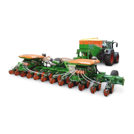
Amazone EDX 9000-TC Service Manual
Precision air planter xpress singling / electronics / hydraulics
Hide thumbs
Also See for EDX 9000-TC
:
Operating manual
(246 pages)
1
2
Table Of Contents
3
4
5
6
7
8
9
10
11
12
13
14
15
16
17
18
19
20
21
22
23
24
25
26
27
28
29
30
31
32
33
34
35
36
37
38
39
40
41
42
43
44
45
46
47
48
49
50
51
52
53
54
55
56
57
58
59
60
61
62
63
64
65
66
67
68
69
70
71
72
73
74
75
76
77
78
79
80
81
82
83
84
85
86
87
88
89
90
91
92
93
94
95
96
97
98
99
100
101
102
103
104
105
106
107
108
109
110
111
112
113
114
115
116
117
118
119
120
121
122
123
124
125
126
127
128
129
130
131
132
133
134
135
136
137
138
139
140
page
of
140
Go
/
140
Contents
Table of Contents
Troubleshooting
Bookmarks
Table of Contents
Table of Contents
Xpress Singling
Recommended Selection of Maize Singling Drum for the EDX System
Presentation Xpress Grain Singling
Flow Bed Shutter
Flow Bed/Seed Shutter
Scraper Setting/Alignment
Hole Covering Rollers/Point of Delivery
Lip Seal
Dismounting the Drum
Dismounting the Scraper
Dismantling the Drum
Installation of the Hole Covering Rollers
Installation of the Scraper Unit
Calibrating the Remote Scraper Bar Adjustment
Installation of the Metering Drum
Factors for Distribution Along the Row
Electronics
Connection
Overview
Main Components of the Electronics - EDX 9000-TC
Main Components of the Electronics - EDX 6000-TC
Main Components of the EDX 6000-2C Electronics
Main Components of the EDX 6000-2FC Electronics
Main Components of the EDX 6000-2 Electronics
Opto-Sensors
Installation Locations of Opto-Sensors
Adjustment Possibilities for the Opto-Sensors
Setting Values in the Diagnostic Input
Opto-Sensor Setting Recommendation
Opto-Sensor Check Sequence
Tramline / Single Row Switching
Installation Locations of Positioning Units
Diagnosis of Positioning Units
Switching Correlations Positioning Units and Mini Job Computer
Weighing Technology EDX 6000-TC
Weighing Technology Setup
Pin Assignment Distributor Box
Calibrating the Weighing T Echnology
Sensors
Sensors Used / Function of EDX
Overview of Sensor Installation Positions - EDX 9000-TC
Overview of Sensor Installation Positions - EDX 6000-TC
Overview of Sensor EDX 6000-2C Installation Positions
Installation Location of Blower Speed Sensor - EDX 6000-TC
Installation Location of Blower Speed Sensor - EDX 6000-2C
Installation Location of Ha Sensor (Radar) - EDX 6000-TC
Installation Location of Pressure Sensor / AMFÜME Seed
Installation Location of Scraper Bar Turn Angle Sensor
Working Position Sensor (AS) EDX 9000-TC & EDX 6000-TC
Working Position Sensor (AS) EDX 6000-2
Drive of the Fertiliser Metering Unit + Speed Sensor EDX 6000-TC
Drive of the Fertiliser Metering Unit + Speed Sensor EDX 6000-2C
PWM - Pulse Width Modulation
Testing Sensors
Overview for Testing the Sensors
Changing to the Setup Menu
Difference between Diagnosis Menu Input and Output
Explanations of Diagnostics Function of AMATRON 3
Testing Sensors Using the Diagnostic Menu
Explanation of Terms - Diagnostic Input
Explanation of Terms - Diagnostic Output
Amatron 3
Setting Values for AMATRON 3
Detecting the Software Versions of the Machine
Displaying the Terminal Version
Troubleshooting Chart
Cable Harness
Pin Assignment of Electric Plugs
Contact Assignment of 42-Pin AMP Plug
Wiring Harness for Hydraulics NL268 EDX 9000 -TC
Wiring Harness for Base NL268 EDX 9000-TC
Wiring Harness for Pressure Adjustment NL459 EDX 9000-TC
Kabelbaum Druckverstellung NL269 / NL270
Wiring Harness for Base NL462 EDX 6000-TC
Wiring Harness for Hydraulics NL292 EDX 6000-TC
Wiring Harness for Base NL463 EDX 6000-2C
Wiring Harness for Base NL469 EDX 6000-2
Faults in the Area of the Electro-Hydraulics
Arrangement of the Solenoid Valves EDX 9000-TC
Arrangement of the Solenoid Valves EDX 6000-TC
Installation Location - Pressure Adjustment of the Coulter EDX 9000-TC
Hydraulic
Hydraulic Circuit of the EDX 9000-TC
Hydraulic Circuit of the EDX 6000-TC
Hydraulic Circuit of the EDX 6000-2C
Repair Instructions
Folding in the Machine in the Event of Failure of the AMATRON 3
Hydraulic Circuit Diagrams EDX 9000-TC
Hydraulic Circuit Diagrams EDX 6000-TC
Hydraulic Diagrams EDX 6000-2C
Advertisement
Quick Links
Download this manual
Service Manual
az
Precision Air Planter
Xpress singling / Electronics / Hydraulics
EDX 9000-TC
EDX 6000-TC
EDX 6000-2/2C/2FC
(For authorised workshops only)
MG4918
BAG0090.1 03.11
Printed in Germany
en
Table of
Contents
Previous
Page
Next
Page
1
2
3
4
5
Advertisement
Table of Contents
Need help?
Do you have a question about the EDX 9000-TC and is the answer not in the manual?
Ask a question
Questions and answers
Related Manuals for Amazone EDX 9000-TC
Farm Equipment Amazone EDX 9000-TC Operating Manual
(246 pages)
Farm Equipment Amazone EDX 6000 TC Operating Manual
Precision airplanter (234 pages)
Farm Equipment Amazone EDX 6000-2 Operating Manual
Precision airplanter (155 pages)
Farm Equipment Amazone ED 302 Operating Manual
Precision airplanter (196 pages)
Farm Equipment Amazone ED 302 Operator's Manual
Precision airplanter (172 pages)
Farm Equipment Amazone EasyCheck Original Operating Manual
(14 pages)
Farm Equipment Amazone EDX 6000-2C Service Manual
Precision air planter xpress singling / electronics / hydraulics (140 pages)
Farm Equipment Amazone ED 902-K Operator's Manual
Precision airplanter (172 pages)
Farm Equipment Amazone AMASPRAY+ Operator's Manual
On-board computer for the use in conjunction with field sprayers (40 pages)
Farm Equipment Amazone AD-P 303 Special Operating Manual
Top mounted seed drills (192 pages)
Farm Equipment Amazone ZA-X Perfect 602 Operating Manual
Fertiliser spreaders (122 pages)
Farm Equipment Amazone Catros 3001 Operator's Manual
Compact disk harrow (90 pages)
Farm Equipment Amazone AD 2500 Special Operating Manual
Seed drills (184 pages)
Farm Equipment Amazone Citan 12001-C Operating Instructions Manual
Large area seed drill (201 pages)
Farm Equipment Amazone AMATRON+ Operator's Manual
Hectare counter (86 pages)
Farm Equipment Amazone Avant 4002-2 Original Operating Manual
Mounted seeding combination (126 pages)
This manual is also suitable for:
Edx 6000-tc
Edx 6000-2
Edx 6000-2c
Edx 6000-2fc
Table of Contents
Print
Rename the bookmark
Delete bookmark?
Delete from my manuals?
Login
Sign In
OR
Sign in with Facebook
Sign in with Google
Upload manual
Upload from disk
Upload from URL


Need help?
Do you have a question about the EDX 9000-TC and is the answer not in the manual?
Questions and answers