
Related Manuals for Cleco BB P2055MA


Summary of Contents for Cleco BB P2055MA
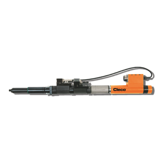
- Page 1 Assembly Instructions P2055MA 2019-09 Fixtured Spindle Series BB For additional product information visit our website at www.ClecoTools.com...
- Page 2 Apex Tool Group. Disclaimer Apex Tool Group reserves the right to modify, supplement, or improve this document or the product without prior notice. Trademark Cleco is a registered trademark of Apex Brands, Inc. Apex Tool Group GmbH Industriestraße 1 73463 Westhausen Germany...
-
Page 3: Table Of Contents
Contents About this document................5 Safety ....................5 General Requirements ....................5 Intended Use ....................... 5 Predictable Misuse ...................... 5 Operator Training ......................5 Personal Protective Equipment ................... 6 Warnings and Notes ....................6 Symbols on the Product ....................6 Principles of safe working.................... - Page 4 P2055MA | 2019-09 Apex Tool Group...
-
Page 5: About This Document
Single action step ation and maintenance of the fastening system to the Sales & Cleco Production Tools Sales & Service same extent and with the same care and attention. Service Center, see last page. •... -
Page 6: Personal Protective Equipment
2.5 Personal Protective Equipment 2.7 Symbols on the Product The motor may heat up and cause burns during removal. Be sure to understand the meaning of each symbol below (max. engine temperature 80 °C). prior to installation, operation or maintenance service. ... -
Page 7: Transport
Careful handling and use of tools Always disconnect the power supply before changing screw bits. Inspect screw bits and retaining ring for visible damage and cracks. Replace damaged parts immediately. Only use screw bits for machine-controlled fastening tools. -
Page 8: Installation
Installation • The Spindle can be mounted in any direction. • Screw the Spindle to a grounded, electro-conductive mounting plate. • Observe the following points during installation: the service panel is accessible for one-off setting of the ARCNET address. warm air must not be produced under the Spindle, also from other components. there are no objects obstructing the air flow at the top or bottom. - Page 9 4.1.2 Size 2 2VK…B 2WK…B Apex Tool Group P2055MA | 2019-09...
- Page 10 4.1.3 Size 3 3VK…B 3WK…B P2055MA | 2019-09 Apex Tool Group...
- Page 11 4.1.4 Size 4 4Z1250A, 4Z1600A 4VK…B 4WK…B Apex Tool Group P2055MA | 2019-09...
-
Page 12: Attaching The Spindle To The Mounting Plate
Attaching the Spindle to the mounting plate VK…B WK…B Size Tightening torques [Nm] +10 % [mm] 12 – 15 P2055MA | 2019-09 Apex Tool Group... -
Page 13: Initial Operation
Initial operation Preset the ARCNET address on each Tightening Mod- ule STM(…) via BCD-code switch: Position the Spindle components together via flat • Always switch off the controller before toothed interfaces, see Service manual. making adjustments. Turn size 1 in 15° increments. •... -
Page 14: Ambient Conditions
Ambient conditions Industrial environment EMC limit class value A, DIN EN 55 0081-2. Enclosure type Ambient tem- Relative Working height Storage tem- according to perature perature humidity DIN 40050 32 to 113 °F 77 to 158 °F 0 to 90 % no con- Up to 3000 m IP40 densation... - Page 16 POWER TOOLS SALES & SERVICE CENTERS Please note that all locations may not service all products. Contact the nearest Cleco® Sales & Service Center for the appropriate facility to handle your service requirements. Sales Center Service Center NORTH AMERICA | SOUTH AMERICA...
Need help?
Do you have a question about the BB P2055MA and is the answer not in the manual?
Questions and answers