Table of Contents
Advertisement
Quick Links
BASIC EXPRESS
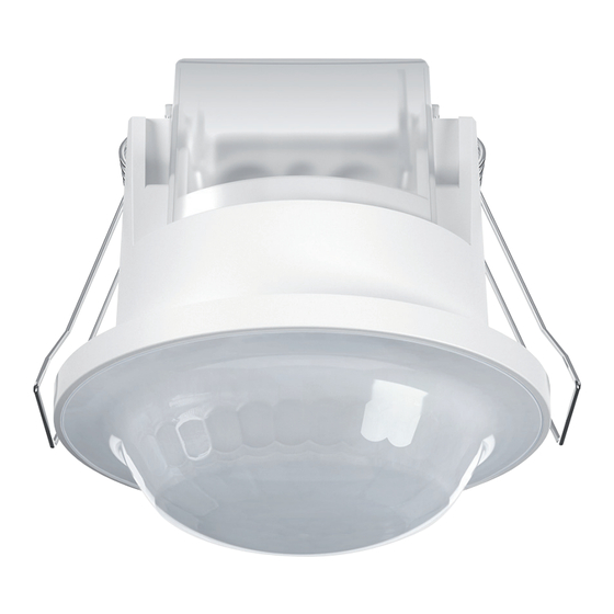
The presence and motion detectors in the BASIC EXPRESS series
provide a simple entry point for intelligent, demand-driven light control.
Their one-piece housing allows for fast, flush-mounted installation in
suspended ceilings. Zero-cross switching means the relay is protected
when the LED lighting is switched, improving energy efficiency and
convenience even when the budget is limited – or in building areas
where simpler functionality is sufficient.
User Manual
| MA02209100 | V1.00 | 20231115
20231115 | EN |
Advertisement
Table of Contents

Related Manuals for ESYLUX BASIC EXPRESS Series


Summary of Contents for ESYLUX BASIC EXPRESS Series
- Page 1 BASIC EXPRESS The presence and motion detectors in the BASIC EXPRESS series provide a simple entry point for intelligent, demand-driven light control. Their one-piece housing allows for fast, flush-mounted installation in suspended ceilings. Zero-cross switching means the relay is protected when the LED lighting is switched, improving energy efficiency and convenience even when the budget is limited –...
- Page 2 An der Strusbek 40 | 22926 Ahrensburg | Germany Subject to change without notice. Reproductions, including translations into other languages or reuse of content for other purposes, may only be authorised by written consent from ESYLUX GmbH. 2 / 29...
-
Page 3: Table Of Contents
Table of contents Table of contents Introduction ............................... 5 Manufacturer/Contact .........................5 Product Identification ...........................5 Content and meaning of the document ..................6 Safety ................................ 6 Intended use ............................6 Staff qualifications ..........................7 Instructions ..............................7 Overview ..............................9 Scope of delivery ........................... 9 Technical data ............................ - Page 4 Table of contents Cleaning and Maintenance ........................26 Maintenance ............................26 Cleaning..............................26 10. Decommissioning ............................27 10.1 Disassembly ............................27 10.2 Disposal ..............................27 4 / 29...
-
Page 5: Introduction
Introduction Manufacturer/Contact If you have questions about the product, need help with the app or are planning extensions, do not hesitate to get in touch with us: ESYLUX GmbH Phone: +49 4102 489-0 An der Strusbek 40 E-mail: info@esylux.com 22926 Ahrensburg Internet: www.esylux.com... -
Page 6: Content And Meaning Of The Document
This document contains detailed information about the installation, configuration and complex functions of the product. The current document is available for download as a PDF at www.esylux.com. It can be printed out if required. • Read the document before using the product. -
Page 7: Staff Qualifications
Safety Staff qualifications Installation, commissioning and other work on the 230 V mains may only be carried out by electricians or electrical specialists in keeping with the country- specific regulations. Configuration and operation can also be performed by individuals with no electrical engineering qualification. - Page 8 Safety WARNING! Risk of fatal injury from interfering with the device. Opening and modifying the device can result in death or serious injury – also for any others working on the system. – Only remove the connection cover of the Powerbox for installation. CAUTION! Risk of injury due to improper installation.
-
Page 9: Overview
Overview Overview Scope of delivery The product scope of delivery comprises: • Device • 2 cable tie for strain relief • Brief instructions for installation and commissioning Technical data Basic Express General Ceiling mounted presence or motion Device category detector Control system ON/OFF Status signalling... - Page 10 Overview Basic Express Max. inrush current 78 A / 5 ms Short pulse/1 min, 2 min, 5 min, Switch-off delay time 10 min, 15 min, 30 min (via ESY-App) Protection type / protection class IP23 / II Operating temperature range -25 °C...+50 °C Test mode Not implemented...
- Page 11 Overview Basic Express Housing Outer diameter Ø 79 mm Housing height 79 mm Material UV-stabilised polycarbonate Colour White, similar to RAL 9010 Protection class IP23 Electrical version Mains voltage 230 V~ ±10 % Mains frequency 50-60 Hz Power consumption 0.4 W Standby consumption <0.4 W Protection class...
-
Page 12: Operation
Operation Operation • 360° field of detection, 8 m range at an installation height of 2.5 m. • Automatically controlled lighting channels when motion is detected. • With zero-cross switching. Detection range 2.5 m mounting height 360° field of detection, 8 m range •... -
Page 13: Conditions In Which The Lighting Is Switched On
Operation Conditions in which the lighting is switched on The lighting is switched on if the target brightness value is below the preset lux value and movement is detected in the field of detection. Further movement is acknowledged by the sensor with two short flashes of the red LED (the LED can be switched off;... -
Page 14: Installation
Installation Installation Mechanical work Description The device is intended for mounting in the ceiling panel of a suspended ceiling. Requirements • There are no cables in the mounting area that could be damaged during drilling. • The installation dimensions shown can be adhered to. WARNING! Switch off the power supply before installing the system. -
Page 15: Circuit Diagram
Installation Circuit diagram L L L‘ L‘ L L L‘ L‘ 10 A Single connection Parallel connection Phase, 230 V Lighting Neutral conductor Push button Electrical work WARNING! Risk of fatal injury from electric shock. Working on the 230 V mains can result in death or serious injury. –... - Page 16 Installation Procedure Open the transparent terminal cover. The terminal cover is fitted with clips on two side. Remove the covers in the connection cover at the points where cables are to be fed through. Remove the insulation on each of the sheathed cables and individual wires.
- Page 17 Installation Lance the cable inlets on the wire gasket and insert the input and output cables through. Connect the 2-way terminal* to connect earth conductors of input and output cables. *The 2-way terminal is not included in delivery. After establishing the electrical connection, fix the installation cable to the housing using cable ties (strain relief).
- Page 18 Installation Close the terminal cover. Insert the device with the mounting folded up into the installation opening. 56.75 mm 30 mm 22.3 mm ø 68 mm 18 / 29...
-
Page 19: Activation
Activation Activation Connect the power supply. A warm-up phase of 45 seconds is initiated. The red LED flashes. During this time, the lighting is switched on. Overview of factory settings Factory settings Operating mode Fully automatic Brightness switching value approx. 500 lux Follow-up time 5 mins Sensitivity... -
Page 20: Configuring Parameters Via Remote Control
Settings Modes activated by pressing the external button: • Press button for approx. 1 seconds: The lighting is switched on or off (for the duration of the switch-off delay time). Press button for approx. 3 seconds: The lighting is switched on or off •... -
Page 21: Mobil-Pdi/Mdi Temporary Settings
Settings Mobil-PDi/MDi temporary settings Parameter configurations are only temporarily applied. Function Customised setting ON / OFF Switching the lighting ON / OFF manually. Note: The “ON / OFF” mode can be cancelled by pressing the “Reset” button. “ON” acknowledgement: Movement detected in the field of detection is acknowledged with two short flashes of the red LED. -
Page 22: Programming The Mobil-Pdi/Mdi
Settings Programming the Mobil-PDi/MDi Alterations to parameters are applied permanently. Function Customised setting Enter programming mode The detector goes into programming mode. Acknowledgement: The red LED lights up permanently and the lighting is switched on continuously. Exit programming mode Programming mode will automatically end 5 minutes after the last parameter set without storing the set parameters. - Page 23 Settings Function Customised setting Fully automatic / semi-automatic mode The lighting can be controlled in fully automatic and semi-automatic modes. Fully automatic: The lighting is switched on depending on the set lux value and movement being detected. If movement is no longer detected, the preset switch-off delay time will start.
- Page 24 Settings Function Customised setting Switch-off delay time The switch-off delay time starts once movement is no longer detected in the field of detection. Acknowledgement: The red LED flashes. PIR sensitivity Settings: maximum (100 %), 75 %, 50 %, minimum (25 %)*. *25%, 50%, 75%, 100% accessible with combination of The sensitivity of the detector for the...
-
Page 25: Troubleshooting
Troubleshooting Troubleshooting Fault Cause Lighting does not switch • Ambient light level is above the preset target brightness value • Lighting has been switched off manually • There are people in the field of detection • There are sources of thermal interference in the field of detection, such as heating, air-conditioning or moving objects (e.g. - Page 26 Cleaning and Maintenance Cleaning and Maintenance Maintenance The ceiling-mounted motion detector does not contain any components that require maintenance. The device can only be replaced as a complete unit. Cleaning No corrosive cleaning agents or solvents may be used for cleaning and care of the device.
- Page 27 Decommissioning Decommissioning 10.1 Disassembly To disassemble the product, work on the 230 V mains is required. This may only be carried out by electrical fitters or qualified electricians. After disconnecting from the 230 V mains, further work can also be carried out by persons without electrical engineering qualifications.
- Page 28 28 / 29...
- Page 29 © ESYLUX GmbH An der Strusbek 40 22926 Ahrensburg Germany Phone: +49 4102 489-0 E-mail: info@esylux.com Internet: www.esylux.com...
Need help?
Do you have a question about the BASIC EXPRESS Series and is the answer not in the manual?
Questions and answers