ESYLUX COMPACT PD-C 360/8 BMS DALI-2 Operating Instructions Manual
Presence detectors
Hide thumbs
Also See for COMPACT PD-C 360/8 BMS DALI-2:
- Operating instructions manual (18 pages) ,
- Manual (4 pages)

Related Manuals for ESYLUX COMPACT PD-C 360/8 BMS DALI-2


Summary of Contents for ESYLUX COMPACT PD-C 360/8 BMS DALI-2
- Page 1 INDOOR AUTOMATION PRESENCE DETECTORS OPERATING INSTRUCTIONS COMPACT • PD-C 360/8 BMS DALI-2 • PD-C 360/24 BMS DALI-2 • PD-C 360/32 BMS DALI-2...
- Page 2 An der Strusbek 40, 22926 Ahrensburg, Germany Details may be subject to change. Copying is only permitted with the written consent of ESYLUX GmbH. This includes translation into other languages and reuse of content for other purposes. 2 / 22...
- Page 3 Inhaltsverzeichnis 1. Informationen zum Dokument Einführung ......................5 Hervorhebungen im Text ...................5 Herstelleradresse .....................6 1.4 Produktidentifizierung ..................6 Warnhinweise ....................7 2. Grundlegende Sicherheitsinformationen Sicherheitshinweise ..................8 Bestimmungsgemäße Verwendung ..............8 Haftung und Schäden ..................9 3. Produktbeschreibung Einführung ......................9 Lieferumfang ....................10 4. Montage 5. Anschluss 6.
- Page 4 10. Entsorgung 11. EU-Konformitätserklärung 12. ESYLUX Herstellergarantie 4 / 22...
-
Page 5: Information About The Document
The current version of this document is available on the respective product page at www .esylux.com and can be printed out in A4 format. Read the operating instructions carefully and observe all safety instructions and warnings. -
Page 6: Manufacturer's Address
Information about the document Manufacturer's address ESYLUX GmbH An der Strusbek 40 22926 Ahrensburg I Germany info@esylux.com www.esylux.com Product identification These instructions apply to the following products: Item number Product name EP10428203 PD-C 360/8 BMS DALI-2 EP10428210 PD-C 360/24 BMS DALI-2... -
Page 7: Basic Safety Information
Basic safety information Warnings Warnings are listed at the start of the relevant chapter if there is a risk of a hazardous situation occurring. The preceding signal words have the following meanings: DANGER! This signal word denotes a hazard involving a high level of risk. Failure to observe the warning will result in death or serious injury. -
Page 8: Intended Use
Basic safety information DANGER! Risk of fatal injury from electric shock! Observe the five safety rules: ¾ Disconnect the power supply Secure the power supply from being switched on again Check that the relevant components have been de-energised 4. Set up the earthing and short-circuiting mechanisms as required 5. -
Page 9: Product Description
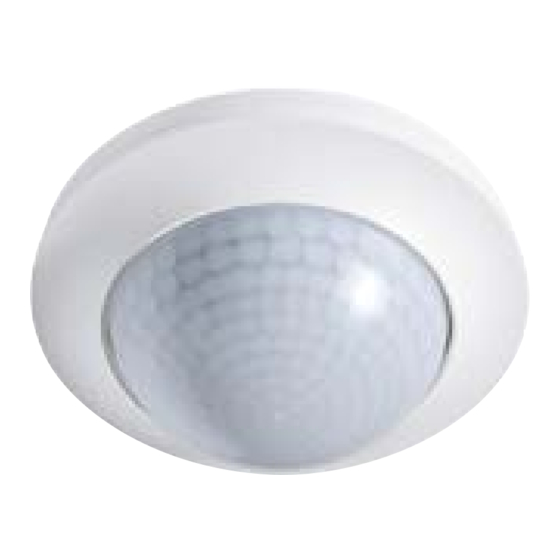
Product description Product description Introduction The COMPACT series DALI-2 BMS presence detector has been developed for intelligently controlling lighting groups in accordance with the DALI-2 standard. It has been designed for integration into a DALI-2 bus system in indoor applications. The DALI-2 BMS presence detector detects movement, light values or push button actuations and converts them into DALI-2 information. -
Page 10: Installation
Installation Installation The following types of installation are possible: with accessory with accessory Installation using the Installation in Installation surface-mounted box* suspended ceilings and using the ceiling flush-mounted boxes installation set* *Required accessories are not included in the scope of delivery. 10 / 22... - Page 11 Connection Connection DANGER! Risk of fatal injury from electric shock! Before connecting, disconnect the bus voltage supply (e.g. APC) at the ¾ mains. Check that the relevant components have been de-energised. ¾ Connect the DALI-2 BMS presence detector: Observe the following wiring diagram and terminal assignment: ¾...
-
Page 12: Initial Operation
Initial operation Initial operation Initial operation is carried out in accordance with the applicable DALI-2 standard. Connect the DALI bus voltage. ¾ A warm-up phase of approx. 25 seconds is initiated. When the green sensor LED briefly flashes three times, the warm-up phase is complete. -
Page 13: Memory Bank
Settings Settings The presence detector is parameterised and controlled only via the application controller (APC). Memory bank 2 The DALI-2 BMS presence detector offers configuration/setting elements that have not yet been defined by the IEC-62386 standards. The following settings can be defined in memory bank 2: •... - Page 14 Settings Value Value bits* Description (decimal) 0000 0010 (Like value = 1) 0000 0011 Sensor LEDs are activated. All events are signalled by the sensor LEDs. Deactivating the 303 instance deactivates the signalling of events in the "Motion detection suppressed" category. This is applied if the sensor does not need to indicate any detected movement.
- Page 15 Settings to compensate for these differences and can be set between 0.1 … 5.0. • 0.1 corresponds to value 1 in memory bank 2 • 5.0 corresponds to value 50 in memory bank 2 Factory setting: ALS correction factor = 1 The DALI-2 BMS presence detector does not perform an ALS correction.
- Page 16 Settings 7.1.5 Memory bank 2 To configure settings in memory bank 2, use standard DALI commands for reading/writing to memory banks. Location Description Memory Value Default RESET value type range value (reference 2) (reference 1) 0x04 LED mode, e.g. LEDs 0 …...
-
Page 17: Maintenance
Maintenance Reference 1: ROM = Read-only memory, cannot be changed by the user. NVM = Non-volatile memory, can be changed by the user. Reference 2: Value is reset to this default value by the "0xFE 0x10 RESET" DALI command. Reference 3: Although some DALI-2 BMS presence detector models use more than one PIR sensor, the sensitivity of all sensors for the device can only be set to the same value once. -
Page 18: Technical Data
Technical data Cleaning CAUTION! Using the wrong cleaning products will damage the device. Do not use corrosive cleaning agents or solvents to clean or maintain the device. Use a lint-free cloth that is either dry or dampened with water. ¾ Technical data Mounting Installation type... - Page 19 Technical data Protection type with accessories IP54 with surface-mounted box (not included in the scope of delivery) Permissible ambient temperature 0 °C…+50 °C Relative humidity 5 - 93 %, non-condensing Colour White, similar to RAL 9010 Electrical design Control system DALI-2 Protection class Nominal voltage 9.5 - 22.5 V Power consumption...
-
Page 20: Eu Declaration Of Conformity
Disposal Channels (lighting / HVAC) Lighting push button input DALI-2 device type Input device in accordance with -301 (push button), input device in accordance with -302 (switch, absolute values), input device in accordance with -303 (presence and motion detectors), input device in accordance with -304 (light sensor) Switch-on time 600 ms... - Page 21 ESYLUX manufacturer's warranty RoHS 2011 / 65 / EU Ecodesign 2009 / 125 / EG ESYLUX manufacturer's warranty ESYLUX manufacturer's warranty at www.esylux.com. Technical and design features may be subject to change. 21 / 22...
- Page 22 22 / 22...
Need help?
Do you have a question about the COMPACT PD-C 360/8 BMS DALI-2 and is the answer not in the manual?
Questions and answers