
Related Manuals for TESTO 175


Summary of Contents for TESTO 175
- Page 1 175 · Data loggers Instruction manual Testo-Direct information@ITM.com 1.800.561.8187 www.
-
Page 2: Table Of Contents
7.2. Cleaning the instrument Tips and assistance 8.1. Questions and answers 8.2. Accessories and spare parts Pos : 3 /TD /Übersc hriften/2. Sic herheit und Umw elt @ 0\m od_1173774719351_79.doc @ 292 @ 1 @ 1 Testo-Direct information@ITM.com 1.800.561.8187 www. -
Page 3: Safety And The Environment
Result of an action. Menu Elements of the instrument, the instrument display or the program interface. [OK] Control keys of the instrument or buttons of the program interface..| ... Functions/paths within a menu. “...” Example entries Testo-Direct information@ITM.com 1.800.561.8187 www. -
Page 4: Ensure Safety
The protection class in the technical data specified for the corresponding instrument may otherwise not be reached. > testo 175 T3 : The maximum permissible difference in potential between the sensor inputs is 50 V. Take this into account when using surface sensors with non- isolated thermocouple. -
Page 5: Specifications
3 Specifications Specifications 3.1. Data loggers testo 175 are used to store and to read out individual readings and measurement series. With testo 175 measurement values are measured, saved and transmitted to the PC via USB cable or SD card, where they can be read out and analysed with the software testo Comfort Software. - Page 6 Measuring cycle 10s - 24h (freely selectable) Interface Mini-USB, SD card slot Memory capacity 1 million readings EU Directive 2014/30/EU, complies with the EN standard12830 testo 175 T2 (0572 1752) Feature Values Measurement Temperature (°C/°F) parameter Sensor type NTC temperature sensor internal and...
- Page 7 2014/30/EU, complies with the EN EU Directive standard12830 6F Please note that, according to EN 12830, this instrument must be regularly checked and calibrated as specified in EN 13486 (recommendation: every year) Contact us for more information. Testo-Direct information@ITM.com 1.800.561.8187 www.
- Page 8 3 Specifications testo 175 T3 (0572 1753) Feature Values Measurement Temperature (°C/°F) parameter Sensor type 2 thermocouples (type K or T) external Measurement -50 to +400 °C (type T) range -50 to +1000 °C (type K) Instrument ±0.5 °C (-50 to +70 °C) ± 1 digit accuracy ±...
- Page 9 3 Specifications testo 175 H1 (0572 1754) Feature Values Measurement Temperature (°C/°F), moisture (%rF parameter /%RH/ °Ctd/ g/m Sensor type NTC temperature sensor, capacitive humidity sensor Number of 2x internal (stubs) measuring channels Measuring -20 to +55 °C ranges -40 to +50 °Ctd...
- Page 10 The following factors have a positive effect on the battery life: • display switched off The battery capacity reading in the display of the data logger is based on the calculated values. However, the Testo-Direct information@ITM.com 1.800.561.8187 www.
-
Page 11: First Steps
1. Open the lock with the key (1). 2. Remove the lock (2) from the locking pin. 3. Pull the locking pin (3) out of the holes in the wall bracket. 4. Slide the data logger out of the wall bracket (4). Testo-Direct information@ITM.com 1.800.561.8187 www. -
Page 12: Inserting Batteries
The software is available in the Internet as a free download requiring registration The instructions for the installation and operation of the software can be found in the testo Comfort Software Basic 5 instruction manual, which can be downloaded together with the software. -
Page 13: Display And Control Elements
5.1. Display The display function can be switched on/off via the software testo Comfort Software. Depending on the operating status, various information may be shown in the display. A detailed representation of the information that can be called up can be found under Menu overview. - Page 14 10 Lower alarm value • Flashes: programmed alarm value is shown • Lights: programmed alarm values were fallen short 11 Upper alarm value • Flashes: programmed alarm value is shown • Lights: programmed alarm values were exceeded Testo-Direct information@ITM.com 1.800.561.8187 www.
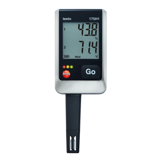
- Page 15 5 Display and control elements testo 175 T2, testo 175 T3, testo 175 H1 1 Reading channel 1 2 Units channel 1 3 Reading channel 2 4 Units channel 2 5 Measurement program over 6 Measurement program running 7 Wait for start of measurement program...
-
Page 16: Led
Limiting value was exceeded/fallen three times short of when pressing the button Yellow LED Instrument changes from Wait-mode flashes three to Rec-mode. times Yellow LED Instrument is in Rec-mode flashes three times when pressing the button Testo-Direct information@ITM.com 1.800.561.8187 www. -
Page 17: Key Functions
The displays appear in the specified sequence. ✓ Instrument is in operating status or End: > Press [GO] in order to change between displays of highest saved reading, lowest saved reading, upper alarm value, lower alarm value, battery life and last reading. Testo-Direct information@ITM.com 1.800.561.8187 www. -
Page 18: Using The Product
> Ensure correct positioning of the sensor to avoid disturbing influences affecting the measurement. > testo 175 T3: Always make sure that you connect the sensor configured (via the software testo Comfort Software) to the individual sockets. The numbers of the connections are printed on the housing. - Page 19 6 Using the product The channels are also activated via the software testo Comfort Software. The symbols for upper or lower alarm value light up in operating states Rec and End, if the programmed alarm value has been exceeded or fallen short off.
- Page 20 ② Upper alarm value reading Start criterion Start criterion key start / PC Date/Time start ③ Lower alarm value ④ Battery capacity in days (see Fig. ① Wait Last reading mode) Measurement value is not saved Testo-Direct information@ITM.com 1.800.561.8187 www.
- Page 21 Rec mode: Start criterion was fulfilled, data logger saves readings ① Last reading ② Highest reading ③ Lowest reading ④ Upper alarm value ⑤ Lower alarm value ⑥ Battery capacity in days Last reading (see Fig. ① Rec mode) Testo-Direct information@ITM.com 1.800.561.8187 www.
- Page 22 – memory full or number of readings) depending on programming ① Last reading ② Highest reading ③ Lowest reading ④ Upper alarm value ⑤ Lower alarm value ⑥ Battery capacity in days Last reading (see Fig. ① End mode) Testo-Direct information@ITM.com 1.800.561.8187 www.
-
Page 23: Mounting The Wall Bracket
The measurement data remain stored in the data logger after they have been read out and can therefore be read out several times. The measurement data will only be deleted when the data logger is reprogrammed. Testo-Direct information@ITM.com 1.800.561.8187 www. - Page 24 3. Push the SD card into the SD card slot (2). The display shows (testo 175 T1) or Sd CArd (testo 175 T2, testo 175 T3, testo 175 H1). 4. Hold [Go] depressed for longer than 2 seconds. The display shows...
-
Page 25: Maintaining The Product
In order to reach the battery life under application temperatures below -10 °C you should use Energizer L92 AAA-size cells. 7. Place the battery compartment cover on the battery compartment. 8. Tighten the screws. The display shows rST. Testo-Direct information@ITM.com 1.800.561.8187 www. -
Page 26: Cleaning The Instrument
9. Connect the data logger to the PC with a USB cable. 10. Start the software testo Comfort Software and set up a connection to the data logger. 11. Reconfigure the data logger or load the old, saved configuration, see separate operating instructions testo Comfort Software. -
Page 27: Tips And Assistance
The battery was changed. No display. data are recorded. > Reprogram the data logger via the software. - - - - Sensor of data logger defective. appears in the display. > Contact your dealer or the Testo Customer Service. Testo-Direct information@ITM.com 1.800.561.8187 www. -
Page 28: Accessories And Spare Parts
Article no. Wall bracket (black) with lock 0554 1702 Mini USB cable to connect the data 0449 0047 logger testo 175 to the PC SD card to read out the data logger 0554 8803 Batteries (alkaline-manganese AAA- 0515 0009 size cells) for applications down to -10 °C...
Need help?
Do you have a question about the 175 and is the answer not in the manual?
Questions and answers