
Related Manuals for TESTO 176


Summary of Contents for TESTO 176
- Page 1 176 · Data loggers Instruction manual GlobalTestSupply www. .com Find Quality Products Online at: sales@GlobalTestSupply.com...
-
Page 2: Table Of Contents
1 Contents Contents Contents ....................31 Safety and the environment ..............32 2.1. About this document ..............32 2.2. Ensure safety................. 33 2.3. Protecting the environment ............33 Specifications ..................34 3.1. Use ....................34 3.2. Technical data ................35 First steps .................... -
Page 3: Safety And The Environment
2 Safety and the environment Safety and the environment 2.1. About this document > Please read this documentation through carefully and familiarize yourself with the product before putting it to use. Pay particular attention to the safety instructions and warning advice in order to prevent injuries and damage to the products. -
Page 4: Ensure Safety
> testo 176 T3 testo 176 T4: The maximum permissible difference in potential between the sensor inputs is 50 V. Take this into account when using surface sensors with non-isolated thermocouple. -
Page 5: Specifications
With its external sensor connections (thermocouples type T, type K and type J) and its robust metal housing the testo 176 T3 is able to perform parallel temperature measurements on up to four measuring locations under extreme conditions. -
Page 6: Technical Data
2 million readings Standards 2014/30/EC, EN 12830 Pos: 20 /TD/Leistungsbeschreibung/Technische Daten/testo 176 T2 @ 6\mod_1278341523355_79.docx @ 63361 @ 5 @ 1 Please note that, according to EN 12830, this instrument must be regularly checked and calibrated as specified in EN 13486 (recommendation: every year) Contact us for more information. - Page 7 Standards 2014/30/EC, EN 12830 Pos : 21 /TD/Leistungs bes chr eibung/T ec hnische D aten/testo 176 T3 @ 6\m od_1278341475870_79.docx @ 63287 @ 5 @ 1 Please note that, according to EN 12830, this instrument must be regularly checked and calibrated as specified in EN 13486 (recommendation: every year) Contact us for more information.
- Page 8 Mini-USB, SD card slot Memory capacity 2 million readings EC Directive 2014/30/EC Pos : 22 /TD/Leistungs bes chr eibung/T ec hnische D aten/testo 176 T4 @ 6\m od_1278341547926_79.docx @ 63393 @ 5 @ 1 GlobalTestSupply www. .com Find Quality Products Online at:...
- Page 9 Mini-USB, SD card slot Memory capacity 2 million readings EC Directive 2014/30/EC Pos : 23 /TD/Leistungs bes chr eibung/T ec hnische D aten/testo 176 H 1 @ 6\m od_1278341570278_79.docx @ 63425 @ 5 @ 1 GlobalTestSupply www. .com Find Quality Products Online at:...
- Page 10 Mini-USB, SD card slot Memory capacity 2 million readings EC Directive 2014/30/EC Pos : 24 /TD/Leistungs bes chr eibung/T ec hnische D aten/testo 176 H 2 @ 6\m od_1278341606049_79.docx @ 63457 @ 5 @ 1 GlobalTestSupply www. .com Find Quality Products Online at:...
- Page 11 Mini-USB, SD card slot Memory capacity 2 million readings EC Directive 2014/30/EC Pos : 25 /TD/Leistungs bes chr eibung/T ec hnische D aten/testo 176 P1 @ 6\mod_1278341642475_79.doc x @ 63489 @ 5 @ 1 GlobalTestSupply www. .com Find Quality Products Online at:...
- Page 12 3 Specifications testo 176 P1 (0572 1767) Feature Values Measurement Temperature (°C/°F), humidity (%rF, %RH, parameter °Ctd, g/m³), barometric pressure (mbar, hPa, psi, inH2O) 2 NTC temperature sensors external or Sensor type 2 capacitive humidity sensors external 1 absolute pressure sensor internal Measurement range 600 mbar to 1100 mbar -20 to +70 °C...
- Page 13 3 Specifications Battery life The programming windows of the software provide you with typical guide values for the expected lifetime of the battery. This lifetime is calculated on the basis of the following factors: • Measuring cycle • Number of connected sensors Since the battery life depends on quite a few other factors, the calculated data can only serve as guide values.
-
Page 14: First Steps
The software is available in the Internet as a free download requiring registration: The instructions for the installation and operation of the software can be found in the testo Comfort Software Basic 5 instruction manual, which can be downloaded together with the software. -
Page 15: Display And Control Elements
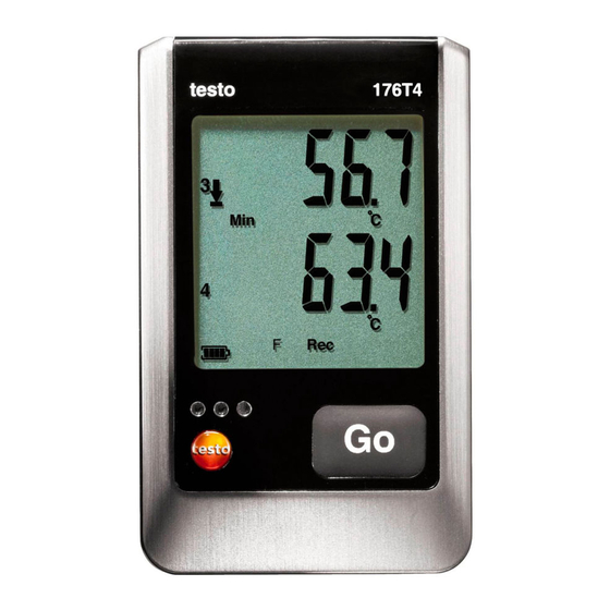
Comfort Software. Display and control elements 5.1. Display The data loggers testo 176 T1, testo 176 T3, testo 176 H2 have no display. The display function can be switched on/off via the testo Comfort Software. Depending on the operating status, various information may be shown in the display. - Page 16 5 Display and control elements testo 176 T2, testo 176 T4, testo 176 H1, testo 176 P1 1 Measurement value channel 1, 2, 3 (depending on number of channels and view) 2 Units channel 1, 2, 3 (depending on number of channels and...
- Page 17 5 Display and control elements 10 Battery capacity Icon Capacity > 151 days < 150 days < 90 days < 60 days < 30 days > Read out data and change battery (see Replacing the battery). 11 Lower alarm value displayed channel (2, 3, 4): •...
-
Page 18: Led
5 Display and control elements 5.2. Representation Explanation Red LED flashes once Remaining battery capacity has dropped every 10 seconds below 30 days Red LED flashes twice Remaining battery capacity has dropped every 10 seconds below 10 days Red LED flashes three Battery is empty: times every 10 seconds Red LED flashes three... -
Page 19: Key Functions
6 Using the product 5.3. Key functions A detailed representation of the screen displays can be found under Menu overview. ✓ Instrument in operating status Wait and start criterion Button start programmed. > Press [GO] for approx. 3 seconds to start the measurement program. -
Page 20: Programming Data Logger
> Ensure correct positioning of the sensor to avoid disturbing influences affecting the measurement. > testo 176 T2, testo 176 T3, testo 176 T4, testo 176 H1, testo 176 H2, testo 176 P1: Make sure that you connect the configured (with the testo Comfort Software) sensors to the individual connections. -
Page 21: Menu Overview
The menu overview shows exemplary display representations of the data logger testo 176 T2. The data loggers testo 176 T1, testo 176 T3, testo 176 H2 have no display. The display must be switched on to be able to show the corresponding indications. - Page 22 6 Using the product Wait-Mode (Wait): Start criterion is programmed, but not yet fulfilled. ① Last ② Upper alarm value reading Start criterion Start criterion key Start criterion Formula start / PC start Date/Time ③ Lower alarm value ④ Battery capacity in days Last measurement value (see Fig.
- Page 23 6 Using the product Rec-Mode (Rec): Start criterion was fulfilled, data logger saves readings End-Mode (End): Measurement program finished (stop criterion reached – memory full or number of readings) depending on programming ① Last reading ② Highest reading ③ Lowest reading ④...
-
Page 24: Mounting The Wall Bracket
6 Using the product 6.4. Mounting the wall bracket The scope of delivery does not include mounting materials (e.g. screws, wall plugs). ✓ The data logger has been removed from the wall bracket. 1. Position the wall bracket at the desired place. 2. - Page 25 4. Plug the USB cable into the Mini USB port (1). 5. Reading out data logger and processing of read out data, see separate operating instructions testo Comfort Software. Via SD card If a data logger is to be read out in Rec-mode, the data...
-
Page 26: Maintaining The Product
7 Maintaining the product Maintaining the product 7.1. Replacing the battery The battery change stops the currently running measuring program. However, stored measurement data are preserved. 1. Read out stored measurement data, see Reading out data. ✓ If it is no longer possible to read out the saved measurement data because the battery capacity is too low: >... -
Page 27: Cleaning The Instrument
9. Connect the data logger to the PC with a USB cable. 10. Start testo Comfort Software and set up a connection to the data logger. 11. Reconfigure the data logger or load the old, saved configuration, see separate operating instructions testo Comfort Software. -
Page 28: Tips And Assistance
The display shows rST. - - - - Sensor of data logger defective or an incompatible sensor has been appears in the display. plugged in. > Contact your dealer or the Testo Customer Service. GlobalTestSupply www. .com Find Quality Products Online at:... -
Page 29: Accessories And Spare Parts
8 Tips and assistance If you have any questions please contact your local dealer or the Testo Customer Service. You find contact data on the back of this document or in the Internet under 8.2. Accessories and spare parts Description Article no.
Need help?
Do you have a question about the 176 and is the answer not in the manual?
Questions and answers