
Related Manuals for TESTO 175


Summary of Contents for TESTO 175
- Page 1 175 · Data loggers Instruction manual DataLoggerStore 1.888. www. .com for Data Logging products online at:...
- Page 2 DataLoggerStore 1.888. www. .com for Data Logging products online at:...
-
Page 3: Table Of Contents
1 Contents Contents Contents Safety and the environment 2.1. About this document 2.2. Ensure safety 2.3. Protecting the environment Specifications 3.1. 3.2. Technical data First steps 4.1. Unlock the data logger 4.2. Inserting batteries 4.3. Connecting the data logger to PC Display and control elements 5.1. -
Page 4: Safety And The Environment
2 Safety and the environment Safety and the environment 2.1. About this document > Please read this documentation through carefully and familiarize yourself with the product before putting it to use. Pay particular attention to the safety instructions and warning advice in order to prevent injuries and damage to the products. -
Page 5: Ensure Safety
The protection class in the technical data specified for the corresponding instrument may otherwise not be reached. > testo 175 T3 : The maximum permissible difference in potential between the sensor inputs is 50 V. Take this into account when using surface sensors with non- isolated thermocouple. -
Page 6: Specifications
3 Specifications Specifications 3.1. Data loggers testo 175 are used to store and to read out individual readings and measurement series. With testo 175 measurement values are measured, saved and transmitted to the PC via USB cable or SD card, where they can be read out and analysed with the software testo Comfort Software. - Page 7 Mini-USB, SD card slot Memory capacity 1 million readings Warranty 24 months, warranty conditions: see website www.testo.com/warranty EC Directive 2004/108/EC, complies with the EN standard12830 testo 175 T2 (0572 1752) Feature Values Measurement Temperature (°C/°F) parameter Sensor type NTC temperature sensor internal and...
- Page 8 Interface Mini-USB, SD card slot Memory capacity 1 million readings Warranty 24 moths, warranty conditions: see website www.testo.com/warranty EC Directive 2004/108/EC, complies with the EN standard12830 Please note that, according to EN 12830, this instrument must be regularly checked and calibrated as specified in EN 13486 (recommendation: every year) Contact us for more information.
- Page 9 3 Specifications testo 175 T3 (0572 1753) Feature Values Measurement Temperature (°C/°F) parameter Sensor type 2 thermocouples (type K or T) external Measurement -50 to +400 °C (type T) range -50 to +1000 °C (type K) Instrument ±0.5 °C (-50 to +70 °C) ± 1 digit accuracy ±...
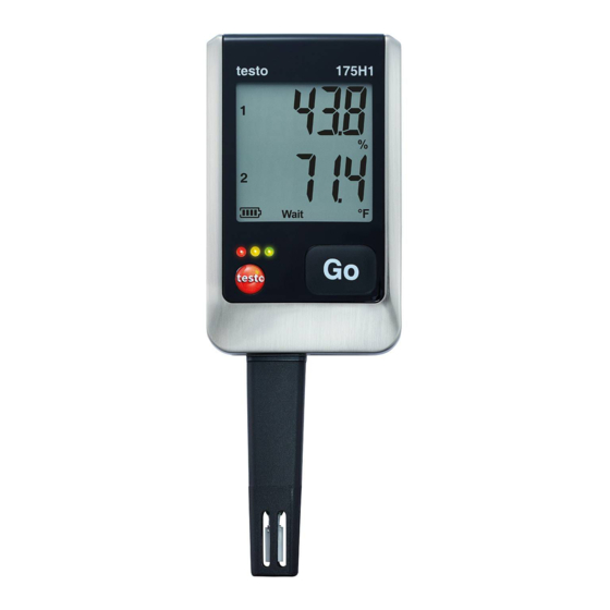
- Page 10 3 Specifications testo 175 H1 (0572 1754) Feature Values Measurement Temperature (°C/°F), moisture (%rF parameter /%RH/ °Ctd/ g/m Sensor type NTC temperature sensor, capacitive humidity sensor Number of 2x internal (stubs) measuring channels Measuring -20 to +55 °C ranges -40 to +50 °Ctd...
- Page 11 Interface Mini-USB, SD card slot Memory capacity 1 million readings Warranty 24 months, warranty conditions: see website www.testo.com/warranty EC Directive 2004/108/EC Battery life The programming windows of the software provide you with typical guide values for the expected lifetime of the battery.
-
Page 12: First Steps
4 First steps data logger is switched off when a critical voltage level has been reached. It may therefore happen that: • readings are still recorded, even though the battery capacity reading says "empty". • the measurement program is stopped, even though the battery capacity reading just before indicated a still remaining battery capacity. -
Page 13: Inserting Batteries
The software is available in the Internet as a free download requiring registration: www.testo.com/download-center. The instructions for the installation and operation of the software can be found in the testo Comfort Software Basic 5 instruction manual, which can be downloaded together with the software. -
Page 14: Display And Control Elements
5 Display and control elements 4. Open the cover. 5. Plug the USB cable into the Mini USB port (1). 6. Configure the data logger, see separate operating instructions testo Comfort Software. Display and control elements 5.1. Display The display function can be switched on/off via the software testo Comfort Software. - Page 15 5 Display and control elements testo 175 T1 1 Highest saved reading 2 Lowest saved reading 3 Reading 4 Units 5 Measurement program over 6 Measurement program running 7 Wait for start of measurement program 8 Start criterion Date/ Time programmed...
- Page 16 11 Upper alarm value • Flashes: programmed alarm value is shown • Lights: programmed alarm values were exceeded testo 175 T2, testo 175 T3, testo 175 H1 1 Reading channel 1 2 Units channel 1 3 Reading channel 2 4 Units channel 2...
-
Page 17: Led
5 Display and control elements Icon Capacity <30 days > Read out data and change battery (see Reading out measurement data page 24). 10 Lower limit value channel 2: • Flashes: programmed alarm value is shown • Lights: programmed alarm values were fallen short 11 Upper limit value channel 2: •... -
Page 18: Key Functions
5 Display and control elements Representation Explanation Yellow LED Instrument changes from Wait-mode to flashes three Rec-mode. times Yellow LED Instrument is in Rec-mode flashes three times when pressing the button Green and Instrument is in End-mode yellow LED flash three times when pressing the button. -
Page 19: Using The Product
> Ensure correct positioning of the sensor to avoid disturbing influences affecting the measurement. > testo 175 T3: Always make sure that you connect the sensor configured (via the software testo Comfort Software) to the individual sockets. The numbers of the connections are printed on the housing. -
Page 20: Menu Overview
6 Using the product 6.3. Menu overview The menu overview shows exemplary display representations of the data logger testo 175-T2. The display must be switched on to be able to show the corresponding indications. This is accomplished with the software testo Comfort Software. - Page 21 6 Using the product Wait mode: Start criterion is programmed, but not yet fulfilled. ① Last ② Upper alarm value reading Start criterion Start criterion key start / PC Date/Time start ③ Lower alarm value ④ Battery capacity in days (see Fig.
- Page 22 6 Using the product Rec mode: Start criterion was fulfilled, data logger saves readings ① Last reading ② Highest reading ③ Lowest reading ④ Upper alarm value ⑤ Lower alarm value ⑥ Battery capacity in days Last reading (see Fig. ① Rec mode) DataLoggerStore 1.888.
-
Page 23: Mounting The Wall Bracket
6 Using the product End mode: Measurement program finished (stop criterion reached – memory full or number of readings) depending on programming ① Last reading ② Highest reading ③ Lowest reading ④ Upper alarm value ⑤ Lower alarm value ⑥ Battery capacity in days Last reading (see Fig. -
Page 24: Securing The Data Logger
6 Using the product 4. Fasten the wall bracket with suitable screws. 6.5. Securing the data logger ✓ The wall bracket has been mounted. 1. Slide the data logger into the wall bracket (1). 2. Push the locking pin (2) through the holes in the wall bracket. -
Page 25: Maintaining The Product
3. Push the SD card into the SD card slot (2). The display shows (testo 175 T1) or Sd CArd (testo 175 T2, testo 175 T3, testo 175 H1). 4. Hold [Go] depressed for longer than 2 seconds. The display shows... - Page 26 9. Connect the data logger to the PC with a USB cable. 10. Start the software testo Comfort Software and set up a connection to the data logger. 11. Reconfigure the data logger or load the old, saved configuration, see separate operating instructions testo Comfort Software.
-
Page 27: Cleaning The Instrument
> Reprogram the data logger via the software. - - - - Sensor of data logger defective. appears in the display. > Contact your dealer or the Testo Customer Service. DataLoggerStore 1.888. www. .com for Data Logging products online at:... -
Page 28: Accessories And Spare Parts
8 Tips and assistance If you have any questions please contact your local dealer or the Testo Customer Service. You find contact data on the back of this document or in the Internet under www.testo.com/service-contact. 8.2. Accessories and spare parts Description Article no. - Page 29 DataLoggerStore 1.888. www. .com for Data Logging products online at:...
- Page 30 0970 1759 en 04 DataLoggerStore 1.888. www. .com for Data Logging products online at:...
Need help?
Do you have a question about the 175 and is the answer not in the manual?
Questions and answers
Import failure message when downloading data. Happens on two different data loggers. How do I fix this?
To fix an import failure message when downloading data from TESTO 175 data loggers, check the following:
1. SD Card Memory: If "FULL" or "Err" appears, the SD card may be full or have an error. Remove the SD card, free up memory, and copy the data.
2. No Data Recorded: If "nO dAtA" appears, the logger is in Wait mode and has not recorded data. Remove the SD card and wait until the logger switches to Rec mode.
3. Battery Change: If "rST" appears, the battery was changed and no data is being recorded. Reprogram the data logger using the software.
4. Sensor Defect: If "----" appears, the sensor may be defective. Contact the dealer or Testo Customer Service.
This answer is automatically generated
Hello Sir, I am Derrick and I have a Testo 175T2 data logger. For some time now, I have been unable to export readings from the data logger after recording. I have attached the error feedback I usually get. Could you please assist in fixing this?
To fix the export issue with the Testo 175T2 data logger, follow these steps:
1. Loosen the screw on the right side of the data logger using a coin.
2. Open the cover and insert the SD card into the SD card slot.
3. The display should show "Sd CArd".
4. Press and hold the [Go] button for more than 2 seconds.
- The display will show "COPY".
- The yellow LED will light up during copying.
- The green LED will flash twice when done, and the display will show "OUT".
5. Remove the SD card and insert it into the SD card slot on your PC.
6. Use the Testo Comfort Software to process the data.
If the issue persists, ensure the SD card is functioning properly and is compatible. Also, confirm that the software is correctly installed on your PC.
This answer is automatically generated