
Related Manuals for SMC Networks LEBH50-X3 Series


Summary of Contents for SMC Networks LEBH50-X3 Series
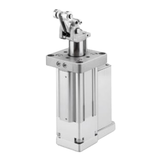
- Page 1 No. DOC1080287 NN67563101 PRODUCT NAME Electric Stopper Cylinder / Controller-less MODEL / Series / Product Number LEBH50・63・80-X3 Series...
-
Page 2: Table Of Contents
Contents Safety Instructions ....................1 1. Outline .......................3 1.1 Features ............................3 1.2 Procedure before operation ..................... 4 2. Product Specifications ................5 2.1 How to Order ..........................5 2.2 Specification ..........................6 2.3 Dimensions ............................. 7 2.4 Construction ..........................10 3. Electric Actuators Precautions ............. 11 Wiring of cables / Common precautions .................. -
Page 3: Safety Instructions
LEBH Series/ Electric Stopper Cylinder Safety Instructions These safety instructions are intended to prevent hazardous situations and/or equipment damage. These instructions indicate the level of potential hazard with the labels of “Caution,” “Warning” or “Danger.” They are all important notes for safety and must be followed in addition to International Standards (ISO/IEC) , and other safety regulations. -
Page 4: Limited Warranty And Disclaimer/Compliance Requirements
LEBH Series/ Electric Stopper Cylinder Safety Instructions Caution We develop, design, and manufacture our products to be used for automatic control equipment, and provide them for peaceful use in manufacturing industries. Use in non-manufacturing industries is not covered. Products we manufacture and sell cannot be used for the purpose of transactions or certification specified in the Measurement Act. -
Page 5: Outline
1. Outline 1.1 Features This electric stopper cylinder can be used as a stopper in a transfer line with no air source. ⚫ Controller is not required - This product controls ON/OFF operation at 24 VDC with no controller. =>Minimizes installation space. Allows easy startup and wiring. ⚫... -
Page 6: Procedure Before Operation
1.2 Procedure before operation If you are using this product for the first time, please refer to the following wiring and operation procedures. ⚫ Actuator wiring Actuator wiring, please to M12 plug connector (A code). M12 connector Connector specification Pin No. Name Function ―... -
Page 7: Product Specifications
2. Product Specifications 2.1 How to Order How to order is shown below. LEBH 50 E K - 30 T L L - □ - X3 Size ● ● Lead ● Option Without option Basic K type D With lock mechanism With cancel cap With lever detection switch Lever direction ●... -
Page 8: Specification
2.2 Specification The basic specifications of this product are shown below. Model LEBH50 LEBH63 LEBH80 Stroke [mm] ∗ Mounting orientation Vertical (extending direction: top) Rising (extending operation) 1 or less 1.5 or less ∗ time [sec] Descending (retracting 1 or less 1.5 or less ∗... -
Page 9: Dimensions
2.3 Dimensions – 7 –... - Page 10 – 8 –...
- Page 11 – 9 –...
-
Page 12: Construction
2.4 Construction When cancel cap is used Component Parts Description Material Note Cylinder tube Aluminium alloy Anodized Rod cover Assembly Housing Aluminium alloy Anodized Lever holder Assembly Guide rod Carbon steel Hard chrome plating Piston rod Carbon steel Hard chrome plating Shock absorber Return box Aluminium alloy... -
Page 13: Electric Actuators Precautions
3. Electric Actuators Precautions Wiring of cables / Common precautions Warning Adjustment, installation, inspection, or wiring changes should be conducted after the power supply to this product has been turned off. Electrical shock, malfunction, or damage can result. Never disassemble the cable. Use only the specified cables. Never connect or disconnect the cable or connector with the power on. - Page 14 11. The speed and force may change depending on the cable length, load, and mounting conditions. Furthermore, if the cable length exceeds 5 m, then it will decrease by up to 10% for every additional 5m. (At 15 m: Reduced by up to 20%) 12.
-
Page 15: Electric Actuators / Common Precautions
Electric actuators / Common precautions Design and selection Warning Be sure to read the operation manual (this manual and the one for the controller: LEC/JXC series). Handling or usage/operation other than that specified in the operation manual may lead to breakage or operation failure of the product. - Page 16 Caution Operate within the limits of the maximum usable stoke. The product will be damaged if it is used with a stroke which exceeds the maximum stroke. Refer to the specifications of the product. When the product repeatedly cycles with partial strokes, operate it at a full stroke at least once a day or every 1000 strokes.
-
Page 17: Mounting
Mounting Warning Keep the manual in a safe place for future reference. The product should be mounted and operated only after thoroughly reading the operation manual and understanding its contents. Observe the tightening torque for screws. Tighten the screws to the recommended torque for mounting the product. Do not make any alterations to this product. -
Page 18: Handling
Handling Warning Do not touch the motor during operation. The surface temperature of the motor can increase to approx. 80°C due to operating conditions. The temperature may also increase due to energization. As it may cause burns, do not touch the motor when in operation. - Page 19 [Grounding] Warning Be certain to ground the actuator. Dedicated grounding should be used. Grounding should be to a D-class ground. (Ground resistance of 100 Ω or less.) Grounding should be performed near the actuator to shorten the grounding distance. The cross-sectional area of this wire shall be a minimum of 2 mm Avoid common grounding with other devices.
-
Page 20: Operating Environment
Operating environment Warning Avoid use in the following environments. a. Areas with large amounts of dust or cutting chips that could enter the product b. Areas where the ambient temperature exceeds the specified range (Refer to the specifications.) c. Areas where the ambient humidity exceeds the specified range (Refer to the specifications.) d. -
Page 21: Maintenance
Maintenance Warning Do not disassemble or repair the product. Fire or electric shock can result. Contact SMC if the disassembly of the product is required for maintenance. Before modifying or checking the wiring, the voltage should be checked with a tester 5 minutes after the power supply has been turned off. -
Page 22: Actuator With Lock / Common Precautions
Actuator with Lock / Common precautions Warning Do not use the lock as a safety brake or as a control that requires a locking force. The lock used for the product with lock is designed to prevent the dropping of workpieces. For vertical mounting, use the product with lock. -
Page 23: Design And Selection
Controller ( Including Driver ) and Peripheral Devices / Common precautions Design and selection Warning Be sure to apply the specified voltage. Otherwise, malfunction or breakage may occur. If the applied voltage is lower than the specified voltage, it is possible that the load will not be able to be moved due to an internal voltage drop of the controller. Please check the operating voltage before use. - Page 24 13. Radiant heat from strong heat sources, such as a furnace, direct sunlight, etc., should not be applied to the product. It will cause failure of the controller or its peripheral devices. 14. Do not use the product in an environment subject to a temperature cycle. It will cause failure of the controller or its peripheral devices.
-
Page 25: Installation
Installation Warning Install the controller and its peripheral devices on a fire-proof material. Direct installation on or near a flammable material may cause a fire. Do not install the product in a place subject to vibrations and impacts. It will cause failure or malfunction. Do not mount the controller and its peripheral devices together with a large-sized electromagnetic contactor or no-fuse breaker, which generate vibration, on the same panel. -
Page 26: Wiring
Wiring Warning Do not apply any excessive force to cables, such as repeated bending, tensioning, or placing a heavy object on the cables. It may cause an electric shock, fire, or the breaking of a wire. Connect wires and cables correctly. Incorrect wiring could break the controller or its peripheral devices depending on the seriousness. -
Page 27: Electric Stopper Cylinder /Specific Product Precautions
4. Electric Stopper Cylinder /Specific Product Precautions 4.1 Design and selection Warning Use within the specified range. If the condition exceeds the specified operating range, it will cause excessive impact or vibration to the actuator, leading to possible damages. If the operating conditions involve load fluctuations, or changes in the frictional resistance, ensure that safety measures are in place to prevent injury to the operator or damage to the equipment. - Page 28 The hole and screw dimension of recommended mounting plate LEBH50 LEBH63 LEBH80 Max. tightening torque Size Bolt [N・m] LEBH50 12.5 LEBH63 24.5 LEBH80 42.0 How to change the relationship between transfer direction and piping position The relationship between the transfer direction and piping position can be changed in increments of 90 degrees.
- Page 29 Auto Switch Mounting Tightening with a torque that exceeds the specified range may cause malfunction, while tightening with a torque below the range may cause misalignment of the gripping position. Auto switch proper mounting Auto switch proper mounting position [mm] position (Detection at Stroke End) Auto switch model D-M9□...
- Page 30 Lever Detection Switch (Proximity Switch) / E2E-X2D1-N Mounting Confirm that the proximity switch indicator LED turns to green when the lever is pushed towards the proximity switch side. (Figure-1) Confirm that the proximity switch indicator LED turns to green when the lever is pushed towards the opposite side from the proximity switch.
-
Page 31: Handling
4.3 Handling Warning Do not put your hand or finger between the lever holder and rod cover. Do not put your hand or finger between the lever holder and the rod cover when lowering the cylinder during adjustment of the shock absorber. Caution Do not let your hand become caught when operating the cylinder. -
Page 32: Maintenance
4.4 Maintenance Warning Perform maintenance inspection according to bellow the procedures indicated in the operation manual. If handled improperly, malfunction and damage of machinery or equipment may occur. Caution The stopping condition of the transferred object may vary due to changes in ambient temperature or changes in the shock absorber resistance over time. -
Page 33: Troubleshooting
5. Troubleshooting Phenomenon Cause Countermeasure “ON” operation / initial 1) The cable is not connected or has Confirm that the cable is connected been disconnected. correctly Piston rod is not fall. 2) The resistance being applied to the Keep the load/resistance within the actuator constantly exceeds... - Page 34 Phenomenon Cause Countermeasure Damage 4) If the next works collides while the Do not allow works to collide while the lever is standing erect (after kinetic lever is standing erect. energy has been absorbed by the shock absorber). Transferred object does not stop. 1) Conveyor adjustment problem Set the conveyor height with in the range from the lower limit position to...
- Page 35 Revision history Completely revised from No.TQ0970003-OM004 June 2024 First edition July 2024 Revision Tel: + 81 3 5207 8249 Fax: +81 3 5298 5362 http://www.smcworld.com Note: Specifications are subject to change without prior notice and any obligation on the part of the manufacturer. ©...
Need help?
Do you have a question about the LEBH50-X3 Series and is the answer not in the manual?
Questions and answers