Table of Contents
Advertisement
Quick Links
Product data sheet
Inverter product series
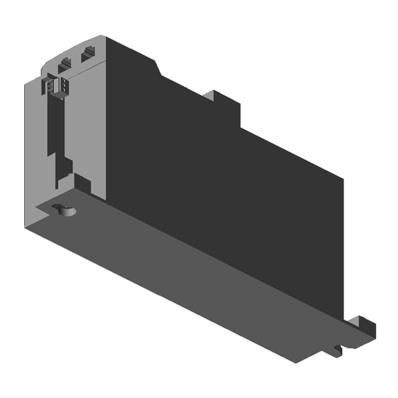
I55BE230F10V1000LS
Note: The model shown is a simplified representation. Minor deviations may occur.
Technical product information
Inverter product series
Inverter
Type
Rated power
Rated power LD
Rated mains voltage
Output current
Output current LD
RFI filter
Output frequency
I/O extension
Fieldbus network
Enclosure
Mounting location
Weight / unit
© Lenze
07/04/2020
I55BE230F10V1000LS
16238805
16238805_3D.stp
16238805_datatable.csv
16238805_datatable.xls
i550 Frequency inverter
i550-C3/400-3
I55BE230F10V1000LS
3 kW/4 HP
4 kW/5 HP
3/PE 400/480 V AC
7.3/6.3 A
8.8/7.6 A
Integrated
0-599 Hz
Standard I/O
PROFINET
IP20
Control cabinet
1.650 KG
www.lenze.com
3D Handling Commands
Rotate
Zoom
Pan
1/2
Advertisement
Table of Contents

Subscribe to Our Youtube Channel
Related Manuals for Lenze I55BE230F10V1000LS


Summary of Contents for Lenze I55BE230F10V1000LS
- Page 1 I55BE230F10V1000LS Product data sheet 16238805 Inverter product series I55BE230F10V1000LS Note: The model shown is a simplified representation. Minor deviations may occur. 3D Handling Commands Rotate Zoom 16238805_3D.stp 16238805_datatable.csv 16238805_datatable.xls Technical product information Inverter product series i550 Frequency inverter Inverter i550-C3/400-3 Type I55BE230F10V1000LS Rated power 3 kW/4 HP Rated power LD 4 kW/5 HP Rated mains voltage 3/PE 400/480 V AC Output current 7.3/6.3 A Output current LD 8.8/7.6 A RFI filter Integrated Output frequency 0-599 Hz I/O extension Standard I/O...
- Page 2 I55BE230F10V1000LS Product data sheet 16238805 1.1 kW ... 4 kW 1.1 kW i550-C1.1/230-1 i550-C1.1/230-2 i550-C1.1/400-3 1.5 kW i550-C1.5/230-1 i550-C1.5/230-2 i550-C1.5/400-3 2.2 kW i550-C2.2/230-1 i550-C2.2/230-2 i550-C2.2/400-3 3 kW i550-C3.0/400-3 4 kW i550-C4.0/400-3 © Lenze 07/04/2020 www.lenze.com...
- Page 3 Operating Instructions | EN Inverter Inverter i550-Cabinet 0.25 ... 132 kW As easy as that.
- Page 4 Overview Overview Hardware overview of the inverter PE connec on X100 Mains connec on/DC bus Relay output Network status LEDs X2xx Network Interface Diagnos c module Memory module Control terminals IT-screws Safety module X105 PTC input Motor connec on X109 Operating Instructions i550-Cabinet...
-
Page 5: Table Of Contents
Contents Content 1 General information .....................4 Commissioning......................18 1.1 Target group ......................... 4 7.1 Keypad module ......................18 1.2 Application as directed ....................4 7.1.1 Functions of the keys ..................19 1.3 Device-specific standards and directives ..............4 7.1.2 Example of the keypad handling ..............19 7.1.3 Quick commissioning - terminal control ............ -
Page 6: General Information
EN 61000-3-2. The complete documentation, further information and tools regarding Lenze products can be • The test voltage for insulation resistance tests between a control potential of 24 V and PE found on the Internet: http://www.Lenze.com must be measured in accordance with EN 61800-5-1. -
Page 7: Identification Of The Products
Safety instructions Identification of the products Safety instructions Basic safety measures 5 5 A E x 1 x x x x xxxx Disregarding the following basic safety measures may lead to severe personal injury and Product type Inverter damage to property! Product family i500 Product i550 •... -
Page 8: Layout Of Warning Notices
Safety instructions Layout of warning notices Residual hazards Safety instructions protect against injury to persons or damage to property. The measures The user must take the residual hazards mentioned into consideration in the risk assessment described for the prevention of hazards must be complied with. for his/her machine/system. -
Page 9: Standards And Operating Conditions
Technical data Technical data Connection to the IT system Standards and operating conditions NOTE Conformities 2014/35/EU, 2014/30/EU TR TC 004/2011, TP TC 020/2011 RoHS 2 2011/65/EU Electrical voltage Approvals CULUS UL 61800-5-1, CSA 22.2 No. 274 Internal components have earth/ground potential if the IT screws are not removed. Energy efficiency Class IE2 EN 50598-2... -
Page 10: Mechanical Installation
Mechanical installation Mechanical installation Dimensions and assembly Rated power Weight X/Y [screws + hole [kW] [kg] [mm] [mm] [mm] [mm] spacing] [mm] [mm] 1-phase mains connection 120 V; without integrated RFI filter I55AExxxA 0.25 ... 0.37 I55AExxxA 0.75 ... 1.1 1.35 1-phase mains connection 230/240 V; with integrated RFI filter I55AExxxB 0.25 ... -
Page 11: Electrical Installation
Electrical installation Electrical installation EMC-compliant installation The drive system (inverter and drive) meet the EMC Directive 2014/30/EU if they are instal- General overview of the connections led according to the guidelines of CE-typical drive systems. The connection diagram is considered exemplary for all voltage and power classes. Deviating The structure in the control cabinet must support the EMC-compliant installation with shiel- mains connection diagrams can be found in the corresponding chapters. -
Page 12: Control Terminals
Electrical installation Control terminals Relay output Standard I/O The relay is not suitable for direct switching of an electromechanical holding brake. Use a corresponding suppressor circuit in case of an inductive or capacitive load. Input/output Terminal X3 Information Relay output Inverter [kW] 0.25 ... -
Page 13: 1-Phase Mains Connection 120 V
Electrical installation 1-phase mains connection 120 V Mains connection Terminal data, 1-phase 120 V 3/N/P AC 208 V ... 240 V I55AxxxA I55AxxxA I55AxxxA I55AxxxA Inverter [kW] 0.25 ... 0.37 0.75 ... 1.1 0.25 ... 1.1 0.25 ... 1.1 Connection Mains connection X100 PE connection Motor connection X105 1/N/PE AC 90 V ... -
Page 14: 1-Phase Mains Connection 230/240 V
Electrical installation 1-phase mains connection 230/240 V Mains connection Terminal data, 1-phase 230/240 V 3/N/PE AC 400 V I55AxxxB I55AxxxA I55AxxxA I55AxxxA Inverter [kW] 0.25 ... 0.75 1.1 ... 2.2 0.25 ... 2.2 0.25 ... 2.2 Connection Mains connection X100 PE connection Motor connection X105 1/N/PE AC 170 V ... 264 V Connection type Pluggable screw terminal PE screw... -
Page 15: 3-Phase Mains Connection 230/240 V
Electrical installation 3-phase mains connection 230/240 V Mains connection Terminal data, 3-phase 230/240 V 3/N/PE AC 208 V ... 240 V I55AxxxD I55AxxxD I55AxxxC I55AxxxX I55AxxxD I55AxxxC Inverter [kW] 0.25 ... 0.75 1.1 ... 2.2 4 ... 5.5 0.25 ... 5.5 0.25 ... 2.2 4 ... 5.5 Connection Mains connection X100 PE connection Motor connection X105 …... -
Page 16: 3-Phase Mains Connection 400 V
Electrical installation 3-phase mains connection 400 V Terminal data, 3-phase 400 V I55AxxxF I55BxxxF I55AxxxF I55AxxxF I55AxxxF I55AxxxF I55AxxxF I55AxxxF I55AxxxF I55BxxxF I55AxxxF I55AxxxF I55AxxxF Inverter [kW] 0.37 ... 2.2 3 ... 4 3 ... 5.5 7.5 ... 11 15 ... 22 0.37 ... 5.5 7.5 ... 11 15 ... - Page 17 Electrical installation Terminal data, 3-phase 400 V Mains connection I55AxxxF I55AxxxF I55AxxxF I55AxxxF I55AxxxF I55AxxxF I55AxxxF I55AxxxF 3/N/PE Inverter [kW] 30 ... 45 55 ... 75 90 ... 132 30 ... 75 90 ... 132 30 ... 45 55 ... 75 90 ... 132 AC 400 V Connection Mains connection X100 PE connection...
-
Page 18: 3-Phase Mains Connection 480 V
Electrical installation 5.10 3-phase mains connection 480 V Terminal data, 3-phase 480 V I55AxxxF I55BxxxF I55AxxxF I55AxxxF I55AxxxF I55AxxxF I55AxxxF I55AxxxF I55AxxxF I55BxxxF I55AxxxF I55AxxxF I55AxxxF Inverter [kW] 0.37 ... 2.2 3 ... 4 3 ... 5.5 7.5 ... 11 15 ... 22 0.37 ... 5.5 7.5 ... 11 15 ... - Page 19 Electrical installation Terminal data, 3-phase 480 V Mains connection I55AxxxF I55AxxxF I55AxxxF I55AxxxF I55AxxxF I55AxxxF I55AxxxF I55AxxxF 3/N/PE Inverter [kW] 30 ... 45 55 ... 75 90 ... 132 30 ... 75 90 ... 132 30 ... 45 55 ... 75 90 ... 132 AC 480 V Connection Mains connection X100 PE connection...
-
Page 20: Commissioning
Initial switch-on Initial switch-on Commissioning DANGER DANGER Electrical voltage Electrical voltage Incorrect wiring can cause unexpected states during the commissioning phase. Incorrect wiring can cause unexpected states during the commissioning phase. ► Wiring must be complete and correct. ► Wiring must be complete and correct. ►... -
Page 21: Functions Of The Keys
Commissioning 7.1.1 Functions of the keys 7.1.3 Quick commissioning - terminal control The following quick overview with graphical parameter representation is sufficient for com- Actuation Action missioning many applications with terminal control. Further setting options are described in Press briefly • Navigation in the menu this document or in the commissioning document. •... -
Page 22: Extended Terminal Control
Digital output 1 A USB module and a standard USB cable (A plug to micro-B plug) is required for this. *P420.02 Release brake GND for analog and digital signals http://www.Lenze.com Relay activated at Relay NO contact *P420.01 Ready for operation... -
Page 23: The Most Important Parameters At A Glance
Commissioning The most important parameters at a glance This chapter contains the most important parameters and selections. You can find a detailed description in the commissioning document. http://www.Lenze.com The parameters are divided into the following function groups: • Pxxx.xx group 0: Favorites •... - Page 24 V/f characteristic control The control mode is used for speed control of an asynchronous motor via a V/f characteristic with speed feedback. (VFC closed loop) This motor control mode is described in the commissioning manual. http://www.Lenze.com P302.00 V/f characteristic Linear Linear characteristic for drives with constant load torque over the speed.
- Page 25 Commissioning Display code Designation Possible settings/value ranges Keypad code Information P323.00 Motor current 0.001 ... 1.700 ... 500.000 A * Setting of the rated motor current according to motor nameplate. P324.00 Max current 0.0 ... 200.0 ... 3000.0 % Maximum overload current of the inverter. P400.01 Inverter enable TRUE...
- Page 26 Commissioning Display code Designation Possible settings/value ranges Keypad code Information P400.18 Setp: Preset B0 Digital input 4 [14] Assignment of a trigger to the “Activate preset (bit 0)” function. Bit with the valency 20 for the bit-coded selection and activation of a parameterized setpoint (preset value). Trigger = FALSE: Bit = “0”.
- Page 27 Commissioning Display code Designation Possible settings/value ranges Keypad code Information P440.02 AO1 function Output frequency Actual output frequency (resolution: 0.1 Hz). Frequency setpoint Actual frequency setpoint (resolution: 0.1 Hz). Analog input 1 Input signal of analog input 1 (resolution: 0.1 %). P440.03 AO1 min.
-
Page 28: Group 2: Basic Setting
Commissioning 7.4.2 Group 2: Basic setting Display code Designation Possible settings Keypad code Information P225.00 Quick stop decelera- 1.0 s Quick stop deceleration time for “MS: Velocity mode” tion time • If the "Quick stop" function is activated, the motor is brought to a standstill within the deceleration time set here. •... -
Page 29: Troubleshooting
Troubleshooting Troubleshooting Error message If an error is pending, the keypad shows the following information. 1 = error text 2 = error type F = fault T = trouble W = warning 3 = error code (hexadecimal) Faults (F) and trouble (T) are displayed continuously. The inverter is disabled. Warnings (W) are displayed every 2 seconds for a short time. -
Page 30: Error Codes
Troubleshooting Error codes Blocking Reset Error code Description Classification Remedy time [s] possible CiA: Continuous overcurrent (inside the device) Fault • Check motor and wiring for short circuit. 2250 • Check brake resistor and wiring. • Check motor circuit (delta connection, star connection). •... - Page 31 Troubleshooting Blocking Reset Error code Description Classification Remedy time [s] possible 24 V supply fault Warning • Check optional external 24V voltage supply (terminal X3/24E), if connected. 5112 • Check mains voltage. 24-V supply overload Warning • Check 24-V output and digital outputs for earth fault or overload. 5180 6280 Trigger/functions connected incorrectly...
-
Page 32: Led Status
Fundamental information on project planning and ordering the product Commissioning document Fundamental information for the installation and commissioning of the product Mounting instructions Fundamental information on mounting the product The documents can be found in the Lenze Doc Finder. Operating Instructions i550-Cabinet... - Page 33 Further documents Operating Instructions i550-Cabinet...
- Page 34 © 01/2020 | 3.0 Lenze Drives GmbH Postfach 10 13 52, 31763 Hameln Breslauer Straße 3, 32699 Extertal GERMANY HR Lemgo B 6478 Phone: +49 5154 82-0 Fax: +49 5154 82-2800 E-mail: Sales.de@Lenze.com Web: www.Lenze.com Lenze Service GmbH Breslauer Straße 3, 32699 Extertal...
Need help?
Do you have a question about the I55BE230F10V1000LS and is the answer not in the manual?
Questions and answers