
Related Manuals for Samson 3276-D


Summary of Contents for Samson 3276-D
- Page 1 EB 8318 EN Translation of original instructions Type 3276-D Pneumatic Actuator Type 3276-R Pneumatic Actuator Type 3276 Pneumatic Actuator Actuator area: 258, 387, 645 and 1032 cm² Edition August 2021...
- Page 2 Note on these mounting and operating instructions These mounting and operating instructions assist you in mounting and operating the device safely. The instructions are binding for handling SAMSON devices. The images shown in these instructions are for illustration purposes only. The actual product may vary.
-
Page 3: Table Of Contents
Contents Safety instructions and measures ..............1-1 Notes on possible severe personal injury ............1-3 Notes on possible personal injury ..............1-4 Notes on possible property damage .............1-5 Warnings on the device ................1-7 Markings on the device ................2-1 Actuator nameplate ..................2-1 Design and principle of operation ...............3-1 Direction of action ..................3-1 Fail-safe action ...................3-8 Versions .....................3-8... - Page 4 Decommissioning ..................9-1 Removal ....................10-1 10.1 Removing the actuator from the valve ............10-2 10.2 Relieving the spring compression in the actuator ..........10-2 Repairs ....................11-1 11.1 Returning devices to SAMSON ..............11-1 Disposal ....................12-1 Annex......................13-1 13.1 Tightening torques ..................13-1 13.2 Spare parts ....................13-11 13.3 After-sales service ...................13-16...
-
Page 5: Safety Instructions And Measures
SAMSON. SAMSON does not assume any liability for damage resulting from the failure to use the de- vice for its intended purpose or for damage caused by external forces or any other external factors. - Page 6 Î Check with the plant operator for details on further protective equipment. Revisions and other modifications Revisions, conversions or other modifications of the product are not authorized by SAMSON. They are performed at the user's own risk and may lead to safety hazards, for example. Fur- thermore, the product may no longer meet the requirements for its intended use.
-
Page 7: Notes On Possible Severe Personal Injury
REACH regulation: Information on safe use of the part affected u www.samsongroup.com > About SAMSON > Material Compliance > REACH If a device contains a substance which is listed as being a substance of very high concern on the candidate list of the REACH regulation, this circumstance is indicated on the SAMSON delivery note. -
Page 8: Notes On Possible Personal Injury
Safety instructions and measures 1.2 Notes on possible personal injury WARNING Crush hazard arising from moving parts. The actuator contains moving parts (actuator stem), which can injure hands or fingers if inserted into the actuator. Î Do not touch the actuator stem or insert hands or finger into the yoke or beneath the actuator stem while the air supply is connected to the actuator. -
Page 9: Notes On Possible Property Damage
Parts that are not tightened far enough may loosen. Observe the specified tightening torques. Risk of actuator damage due to the use of unsuitable tools. Certain tools are required to work on the actuator. Î Only use tools approved by SAMSON. EB 8318 EN... - Page 10 Safety instructions and measures NOTICE Risk of actuator damage due to the use of unsuitable lubricants. The lubricants to be used depend on the actuator material. Unsuitable lubricants may corrode and damage surfaces. Î Only use lubricants approved by SAMSON. EB 8318 EN...
-
Page 11: Warnings On The Device
Meaning of the warning Location on the device Warning against the incorrect use of the lifting eyelet/eyebolt or swivel hoist on SAMSON actua- tors. Only attach load-bearing slings to them to verti- cally lift the actuator on its own (without the valve). - Page 12 EB 8318 EN...
-
Page 13: Markings On The Device
Markings on the device 2 Markings on the device 2.1 Actuator nameplate The nameplate is affixed to the valve body. It includes all details required to identify the de- vice: 1 Type number Icons representing actuator versions: 2 Data Matrix code Version R, Version D, 3 Number code... - Page 14 EB 8318 EN...
-
Page 15: Design And Principle Of Operation
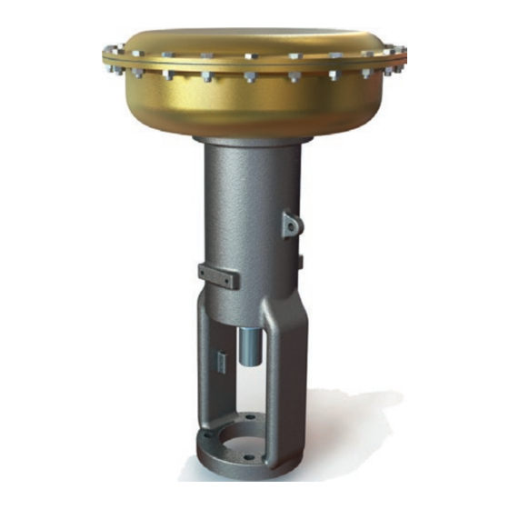
− Version R (reverse-acting, actuator stem See Fig. 3-1 to Fig. 3-5 extends) The SAMSON Type 3276 Actuators are With direction of action "actuator stem mounted to Series 590 Valves (globe valves). extends", the compressed air is applied The actuator mainly consists of a housing... - Page 16 Design and principle of operation Fig. 3-1: Type 3276-D Actuator · Fail-open (actuator stem retracts) Legend for Fig. 3-1 and Fig. 3-2 Screw (to fasten Diaphragm stud (top- Housing with yoke diaphragm base and mounted handwheel) Actuator stem cover) 1030 Housing nut (top- Spring...
- Page 17 Design and principle of operation 1030 1031 1034 Fig. 3-2: Type 3276-D Actuator with top-mounted handwheel (actuator stem retracts) EB 8318 EN...
- Page 18 Design and principle of operation Fig. 3-3: Type 3276-D Actuator with side-mounted handwheel (actuator stem retracts) EB 8318 EN...
- Page 19 Design and principle of operation Legend Housing with yoke Handwheel Handwheel housing Drive (handwheel) Drive nut Bearing bushing (handwheel) Lever arm Drive pin (lever arm) Pivot pin (lever arm) Clamping bolt Bolt Bushing for pivot pin (lever arm) Bearing Stop bolt (side-mounted handwheel) Stop nut (side-mounted handwheel) Washer Ball...
- Page 20 Design and principle of operation Fig. 3-4: Type 3276-R Actuator (actuator stem extends) Legend for Fig. 3-4 and Fig. 3-5 Housing with yoke Yoke flange Seal (bottom diaphragm case) Actuator stem Spring adjuster Travel indicator Setting bolt Stem connector Handwheel housing Washer Actuator diaphragm Drive (handwheel) Spring Screw (bottom diaphragm...
- Page 21 Design and principle of operation 1030 1027 1029 Fig. 3-5: Type 3276-R Actuator with top-mounted handwheel (actuator stem extends) EB 8318 EN...
-
Page 22: Fail-Safe Action
Actuator are available with 258, 387, The listed fail-safe actions apply to 645 and 1032 cm² actuator areas SAMSON Series 590 Valves (globe valves). Version with handwheel All versions can be fitted with an additional When the signal pressure is reduced or the top-mounted handwheel (see Fig. 3-2 and... - Page 23 Design and principle of operation EB 8318 EN...
-
Page 24: Technical Data
Design and principle of operation 3.5 Technical data The nameplate provides information on the actuator version (see the 'Markings on the device' section). Note More information is available in Data Sheet u T 8318. Table 3-1: Technical data for Type 3276 Type 3276 Version D Version R Maximum permissible signal 80 psi (5.5 bar) - Page 25 1) 0.4 to 2 13377 – – – – 1) 0.2 to 1 31660 28984 – – – 1) 1) Type 3276-D 0.4 to 2 27646 22295 – – – 1) 1) 0.2 to 1 52082 49228 46375 – – 1) 1)
- Page 26 Design and principle of operation Table 3-4: See Fig. 3-6 and Fig. 3-8 for dimensions and weights of Type 3276-D Version Type 3276-D 320D 330D 350D 350D 380D 390D Actuator area [cm²] 1032 Travel (mm) Without handwheel Weight With handwheel (top) [kg] With side-mounted handwheel ¼...
- Page 27 Design and principle of operation Ø D Ø D Ø D Type 3276-D without hand- Type 3276-D with top-mounted Type 3276-D with side-mounted wheel handwheel handwheel Fig. 3-6: Dimensional drawings for Type 3276-D EB 8318 EN 3-13...
- Page 28 Design and principle of operation Table 3-5: See Fig. 3-7 and Fig. 3-8 for dimensions and weights of Type 3276-R Version Type 3276-R 320R 330R 350R 350R 380R 390R Actuator area [cm²] 1032 Travel (mm) Without handwheel Weight With handwheel (top) [kg] With side-mounted hand- wheel ¼...
- Page 29 Design and principle of operation Ø D Ø D Ø D Type 3276-R without hand- Type 3276-R with top-mounted Type 3276-R with side-mounted wheel handwheel handwheel Fig. 3-7: Dimensional drawings for Type 3276-R EB 8318 EN 3-15...
- Page 30 Design and principle of operation Actuator stem retracted Ø D Ø D Ø D Ø D N x Schraube Fig. 3-8: Dimensional drawing of housing connections 3-16 EB 8318 EN...
-
Page 31: Shipment And On-Site Transport
Risk of lifting equipment tipping over and damage. Report any damage to risk of damage to lifting accessories due to SAMSON and the forwarding agent (re- exceeding the rated lifting capacity. fer to delivery note). Î Only use approved lifting equipment and 3. -
Page 32: Transporting The Actuator
− Protect the actuator against moisture and Only use the lifting eyelets/eyebolts or swivel dirt. hoist on SAMSON actuators to lift the actua- − Observe permissible temperatures (see tor without the valve. Do not use these lash- 'Technical data' in the 'Design and prin- ing points to lift the entire control valve as- ciple of operation' section). - Page 33 Shipment and on-site transport 1. Replace two bolts on opposite sides of In order to lift an entire control valve assem- the diaphragm case with eyebolts or bly, the slings attached to the valve body swivel hoists. must bear the entire load. The slings between the lashing points on the actuator and rig- 2.
-
Page 34: Storing The Actuator
Î Observe the storage instructions. Special storage instructions for elastomers Î Avoid long storage times. Î Contact SAMSON in case of different Elastomer, e.g. actuator diaphragm storage conditions or longer storage − To keep elastomers in shape and to pre- times. - Page 35 Shipment and on-site transport Our after-sales service can provide more de- tailed storage instructions on request. EB 8318 EN...
- Page 36 EB 8318 EN...
-
Page 37: Installation
(e.g. due to operation' section seizing up after remaining in the same Depending on the version, SAMSON control position for a long time), release any valves are either delivered with the actuator stored energy in the actuator (e.g. spring compression). -
Page 38: Pneumatic Connection
The up- Î Only use tools approved by SAMSON. per signal pressure range value is the same as the maximum value of the bench range or 5.2.1... -
Page 39: Mounting The Actuator Onto The Valve
Installation Determining the lower and upper signal NOTICE pressure range values Risk of actuator damage due to excessively 1. Turn the spring adjuster (906) clockwise high supply pressure. until loading of the actuator spring (595) Î Do not allow the supply pressure to ex- starts. - Page 40 Installation 2. Thread the lock nut and travel indicator 4. Fasten the valve bonnet and actuator (921) downward on the plug stem of the yoke together. Observe tightening valve. torques. 3. Place the actuator with the yoke first ver- 5. Connect the signal pressure. See sec- tically onto the valve bonnet while align- tion 5.2.1.
-
Page 41: Operation
The actuator is operated with air. As a result, mation. air is vented during operation. Î Add any new values to the nameplate. If Î Wear eye and hearing protection when necessary, contact SAMSON to obtain a working near the actuator. new nameplate. WARNING WARNING 6.1 Throttling service... -
Page 42: Neutral Position Of Top-Mounted Handwheel
Operation 6.2.1 Neutral position of top- mounted handwheel Version D The handwheel is in the neutral position when it is turned to the top position (see Fig. 3-2 in the 'Design and principle of oper- ation' section). Version R The handwheel is in the neutral position when it is turned to the lowest position (see Fig. 3-5 in the 'Design and principle of oper- ation' section). -
Page 43: Malfunctions
Malfunctions 7 Malfunctions Read hazard statements, warnings and caution notes in the 'Safety instructions and mea- sures' section. 7.1 Troubleshooting Malfunction Possible reasons Recommended action Actuator stem does not Actuator is blocked. Check attachment. move on demand. Remove the blockage. WARNING! A blocked actuator (e.g. -
Page 44: Emergency Action
Malfunctions 7.2 Emergency action Plant operators are responsible for emergen- cy action to be taken in the plant. EB 8318 EN... -
Page 45: Servicing
Î Add any new values to the nameplate. If The actuator is operated with air. As a result, necessary, contact SAMSON to obtain a air is vented during operation. new nameplate. Î Wear eye and hearing protection when working near the actuator. -
Page 46: Periodic Testing
NOTICE Risk of actuator damage due to the use of 8.2 Preparing the valve for unsuitable tools. Î Only use tools approved by SAMSON. service work 1. Lay out the necessary material and tools NOTICE to have them ready for the intended Risk of actuator damage due to the use of work. -
Page 47: Installing The Valve After Service Work
Replacing the dia- − New diaphragm (911) phragm − Diaphragm holder (902) with silicone 9. Use the screw (914) to fasten the parts a) Type 3276-D (actuator stem onto the actuator stem (61). Observe tightening torque. retracts) 10. Insert the newly assembled diaphragm... - Page 48 Servicing b) Type 3276-R (actuator stem 11. Mount the bushing (903) including the O-rings (924, 925) and the retaining extends) ring (918). 12. Place the parts on the actuator stem in Version without handwheel and version the specified order: with side-mounted handwheel −...
-
Page 49: Replacing The Gaskets (Type 3276-R/Fail-Close Only)
Servicing 6. Lift off the top diaphragm case (850). 17. Use the screw (914) to fasten the parts onto the actuator stem (61). Observe 7. Pull the diaphragm plate assembly con- tightening torque. sisting of the diaphragm plate (901), screw (914), actuator stem (61), dia- 18. - Page 50 Servicing phragm (911) and diaphragm holder 14. Unscrew the screw (914) from the actua- (902) into the top position. tor stem (61). 4. Remove the retaining ring (918) and 15. Take the diaphragm plate (901), dia- then the bushing (903) including the phragm (911) and diaphragm holder O-rings (924, 925).
- Page 51 Servicing − It loads the spring (see 'Setting the actua- Make sure that the actuator stem is not tor' in the 'Installation' section). damaged. 11. Unscrew the two screws (915) opposite 25. Place on the top diaphragm case (850) each other on the bottom diaphragm and fasten it to the bottom diaphragm case (900) and replace them with longer case (900) using the nuts (917), bolts...
-
Page 52: Ordering Spare Parts And Operating Supplies
(918). Contact your nearest SAMSON subsidiary 24. Place the parts on the actuator stem in or SAMSON's After-sales Service for infor- the specified order: mation on spare parts, lubricants and tools. − Diaphragm holder (902) with silicone −... -
Page 53: Decommissioning
Decommissioning 9 Decommissioning WARNING WARNING The work described in this section is only to Crush hazard arising from the moving be performed by personnel appropriately actuator stem. qualified to carry out such tasks. Î Do not insert hands or finger into the yoke while the air supply is connected to the actuator. - Page 54 EB 8318 EN...
-
Page 55: Removal
Removal 10 Removal WARNING WARNING The work described in this section is only to Crush hazard arising from the moving be performed by personnel appropriately actuator stem. qualified to carry out such tasks. Î Do not touch the actuator stem or insert hands or finger into the yoke while the air supply is connected to the actuator. -
Page 56: Removing The Actuator From The Valve
Removal 10.1 Removing the actuator 1. Unscrew the two screws (915) opposite each other on the bottom diaphragm from the valve case (900) and replace them with longer See images in the 'Design and principle of screws, which stick out of the actuator operation' section housing (40) by approx. -
Page 57: Repairs
Î Do not perform any repair work on your side of your shipment so that the docu- own. ments are clearly visible. Î Contact SAMSON's After-sales Service 4. Send the shipment to the address given for repair work. on the RMA. - Page 58 11-2 EB 8318 EN...
-
Page 59: Disposal
Disposal 12 Disposal Î Observe local, national and internation- al refuse regulations. Î Do not dispose of components, lubricants and hazardous substances together with your household waste. EB 8318 EN 12-1... - Page 60 12-2 EB 8318 EN...
-
Page 61: Annex
Annex 13 Annex 13.1 Tightening torques Table 13-1: 330D version Tightening torque in Nm Target value (max. value) With top- With side- Without mounted mounted handwheel handwheel handwheel 49.31 Threaded pin GR 8.8 (98.61) 30.23 Stem connector screw GR 8.8 – (60.46) Screw (to fasten 49.31 diaphragm base and GR 8.8... - Page 62 Annex Tightening torque in Nm Target value (max. value) With top- With side- Without mounted mounted handwheel handwheel handwheel 14.02 1951 Ring bolt GR 18.8 (18.23) Table 13-2: 350D version Tightening torque in Nm Target value (max. value) With top- With side- Without mounted mounted handwheel...
- Page 63 Annex Tightening torque in Nm Target value (max. value) With top- With side- Without mounted mounted handwheel handwheel handwheel 49.31 Diaphragm stud GR 8.8 – – (98.61) 14.50 Stem connector screw GR 8.8 – (28.99) 29.24 1951 Ring bolt GR 18.8 (38.01) Table 13-3: 380D version Tightening torque in Nm Target value (max.
- Page 64 Annex Tightening torque in Nm Target value (max. value) With top- With side- Without mounted mounted handwheel handwheel handwheel 49.31 Spacer bolt (lever arm) GR 8.8 – (98.61) Housing bolt (side- 14.50 GR 8.8 – mounted handwheel) (28.99) 49.31 Diaphragm stud GR 8.8 – –...
- Page 65 Annex Tightening torque in Nm Target value (max. value) With top- With side- Without mounted mounted handwheel handwheel handwheel 49.31 Stop bolt GR 8.8 – (98.61) Threaded pin 6.06 GR 8.8 – (handwheel housing) (12.13) 49.31 Spacer bolt (lever arm) GR 8.8 – (98.61) Housing bolt (side- 14.50 GR 8.8...
- Page 66 Annex Table 13-5: 330R version Tightening torque in Nm Target value (max. value) With top- With side- Without mounted mounted handwheel handwheel handwheel 49.31 Threaded pin GR 8.8 (98.61) 30.23 Stem connector screw GR 8.8 – (60.46) 49.31 – Screw (to fasten GR 8.8 (98.61) diaphragm base and –...
- Page 67 Annex Tightening torque in Nm Target value (max. value) With top- With side- Without mounted mounted handwheel handwheel handwheel 14.02 GR 18.8 – (18.23) 1951 Ring bolt 14.50 GR 8.8 – (18.84) Table 13-6: 350R version Tightening torque in Nm Target value (max. value) With top- With side- Without...
- Page 68 Annex Tightening torque in Nm Target value (max. value) With top- With side- Without mounted mounted handwheel handwheel handwheel Housing bolt (side- 14.50 GR 8.8 – mounted handwheel) (28.99) 49.31 Diaphragm stud GR 8.8 – – (98.61) 14.50 Stem connector screw GR 8.8 – (28.99) 49.31 1029...
- Page 69 Annex Tightening torque in Nm Target value (max. value) With top- With side- Without mounted mounted handwheel handwheel handwheel 49.31 Stop bolt GR 8.8 – (98.61) Threaded pin 6.06 GR 8.8 – (handwheel housing) (12.13) 49.31 Spacer bolt (lever arm) GR 8.8 – (98.61) Housing bolt (side- 231.59 GR 8.8...
- Page 70 Annex Tightening torque in Nm Target value (max. value) With top- With side- Without mounted mounted handwheel handwheel handwheel A479 Pin (threaded bushing) – T410 (78) 152.14 Clamping bolt F-114 " – (304.27) 15.90 Bolt F-112 – (31.80) 49.31 Stop bolt GR 8.8 –...
-
Page 71: Spare Parts
Annex 13.2 Spare parts Housing with yoke Nut (diaphragm case) Actuator stem Retaining ring (bushing) Setting bolt Travel indicator nut Threaded pin Screw (travel indicator) Key drive Travel indicator Washer Vent plug Spring O-ring (bottom diaphragm case) Handwheel Internal O-ring (bushing) Lifting eyelet External O-ring (bushing) Handwheel pin... - Page 72 Annex Bearing 1241 Bottom protector bolt (top-mounted handwheel) Stop bolt (side-mounted handwheel) 1338 Lever arm assembly Stop nut (side-mounted handwheel) 1951 Ring bolt 2250 Washer (bottom diaphragm case) Washer Threaded pin (handwheel housing) Spacer bolt (lever arm) Spacer nut (lever arm) Spacer washer (lever arm) Ball Spring...
- Page 73 Annex Type 3276-D Actuator 1330 1331 1034 1032 1033 EB 8318 EN 13-13...
- Page 74 Annex Version with side-mounted handwheel 941 949 13-14 EB 8318 EN...
- Page 75 Annex Type 3276-R Actuator 1030 1031 1027 1029 EB 8318 EN 13-15...
-
Page 76: After-Sales Service
You can reach our after-sales service at aftersalesservice@samsongroup.com. Addresses of SAMSON AG and its subsid- iaries The addresses of SAMSON AG, its subsid- iaries, representatives and service facilities worldwide can be found on our website (www.samsongroup.com) or in all SAMSON product catalogs. - Page 80 EB 8318 EN SAMSON AKTIENGESELLSCHAFT Weismüllerstraße 3 · 60314 Frankfurt am Main, Germany Phone: +49 69 4009-0 · Fax: +49 69 4009-1507 samson@samsongroup.com · www.samsongroup.com...
Need help?
Do you have a question about the 3276-D and is the answer not in the manual?
Questions and answers