Samson 3271 Mounting And Operating Instructions
Pneumatic actuator
Hide thumbs
Also See for 3271:
- Mounting and operating instructions (76 pages) ,
- Original instructions manual (72 pages) ,
- Mounting and operating instruction (112 pages)

Related Manuals for Samson 3271


Summary of Contents for Samson 3271
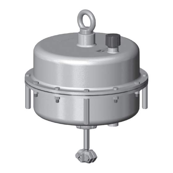
- Page 1 EB 8310-2 EN Translation of original instructions Type 3271 Pneumatic Actuator Type 3271 Pneumatic Actuator Actuator area: 1000 cm² Edition August 2020...
- Page 2 Note on these mounting and operating instructions These mounting and operating instructions assist you in mounting and operating the device safely. The instructions are binding for handling SAMSON devices. The images shown in these instructions are for illustration purposes only. The actual product may vary.
-
Page 3: Table Of Contents
Contents Safety instructions and measures ..............1-1 Notes on possible severe personal injury ............1-3 Notes on possible personal injury ..............1-4 Notes on possible property damage .............1-5 Warnings on the device ................1-6 Markings on the device ................2-1 Actuator nameplate ..................2-1 Design and principle of operation ...............3-1 Direction of action ..................3-2 Signal pressure routing ................3-2 Fail-safe action ...................3-2... - Page 4 Removal ....................11-1 11.1 Removing the actuator from the valve ............11-2 11.2 Relieving the spring compression in the actuator ..........11-2 Repairs ....................12-1 12.1 Returning devices to SAMSON ..............12-1 Disposal ....................13-1 Certificates ....................14-1 Annex......................15-1 15.1 Tightening torques, lubricants and tools ............15-1 15.2 Spare parts ....................15-1...
-
Page 5: Safety Instructions And Measures
SAMSON. SAMSON does not assume any liability for damage resulting from the failure to use the de- vice for its intended purpose or for damage caused by external forces or any other external factors. - Page 6 Î Check with the plant operator for details on further protective equipment. Revisions and other modifications Revisions, conversions or other modifications of the product are not authorized by SAMSON. They are performed at the user's own risk and may lead to safety hazards, for example.
-
Page 7: Notes On Possible Severe Personal Injury
Safety instructions and measures Referenced standards and regulations According to the ignition risk assessment performed in accordance with EN 13463-1:2009, section 5.2, the non-electrical actuators do not have their own potential ignition source even in the rare incident of an operating fault. As a result, they do not fall within the scope of Directive 2014/34/EU. -
Page 8: Notes On Possible Personal Injury
Safety instructions and measures 1.2 Notes on possible personal injury WARNING Crush hazard arising from moving parts. The actuator contains moving parts (actuator stem), which can injure hands or fingers if inserted into the actuator. Î Do not touch the actuator stem or insert hands or finger into the yoke or beneath the actuator stem while the air supply is connected to the actuator. -
Page 9: Notes On Possible Property Damage
Risk of actuator damage due to the use of unsuitable tools. Certain tools are required to work on the actuator. Î Only use tools approved by SAMSON (u AB 0100). Risk of actuator damage due to the use of unsuitable lubricants. The lubricants to be used depend on the actuator material. Unsuitable lubricants may corrode and damage surfaces. -
Page 10: Warnings On The Device
Meaning of the warning Location on the device Warning against the incorrect use of the lifting eyelet/eyebolt or swivel hoist on SAMSON actua- tors. Only attach load-bearing slings to them to verti- cally lift the actuator on its own (without the valve). -
Page 11: Markings On The Device
13 Symbol indicating fail-safe action Actuator stem extends (FA) Actuator stem retracts (FE) Manual override 14 Diaphragm material 15 Connecting thread 16 Date of manufacture 17 Data Matrix code Mat: S/N: 11/12 Fig. 2-1: Nameplate of Type 3271 Actuator EB 8310-2 EN... - Page 12 EB 8310-2 EN...
-
Page 13: Design And Principle Of Operation
Design and principle of operation 3 Design and principle of operation The SAMSON Type 3271 Actuator with sion, taking into account the rated travel. The 1000 cm² actuator area is mounted onto travel is proportional to the signal pressure globe valves. . The direction of action of the actuator... -
Page 14: Direction Of Action
(A10) and diaphragm plate (A5) are arranged in the actuator. The listed fail-safe actions apply to SAMSON globe valves. With direction of action "actuator stem ex- tends", the compressed air is applied to the When the signal pressure is reduced or the... -
Page 15: Actuator Stem Retracts
Various valve accessories according to extends or retracts). IEC 60534-6-1 and NAMUR recommenda- − Side-mounted handwheel tion can be mounted on SAMSON control valves designed according to the modular The actuator can be combined with a principle. See associated valve documenta- Type 3273 Side-mounted Handwheel... - Page 16 (NBR) and is be- tween –35 and +90 °C (–31 and +194 °F) for throttling service. In on/off service, the lowest temperature restricted to –20 °C (–4 °F). Table 3-1: Dimensions in mm and weights in kg Actuator Type 3271 Actuator area cm² 1000 1) rated Height 2) Travel limitation ØD...
- Page 17 Design and principle of operation Dimensional drawings ØD2 ØD2 Ød Ød ØD ØD Standard version of Type 3271 Type 3271 with travel stop EB 8310-2 EN...
- Page 18 EB 8310-2 EN...
-
Page 19: Shipment And On-Site Transport
Risk of lifting equipment tipping over and damage. Report any damage to risk of damage to lifting accessories due to SAMSON and the forwarding agent exceeding the rated lifting capacity. (refer to delivery note). Î Only use approved lifting equipment and 3. -
Page 20: Transporting The Actuator
Shipment and on-site transport 4.3.2 Lifting the actuator Î Do not attach load-bearing slings to the travel stop. To mount large actuators onto the valve, use Î Observe lifting instructions (see sec- lifting equipment (e.g. crane or forklift) to lift tion 4.3.2). - Page 21 Shipment and on-site transport Fig. 4-1: Ring bolt Fig. 4-3: Eyebolt cover in place on the eyebolt Fig. 4-4: Eyebolt cover (with strap) opened Fig. 4-2: Swivel hoist Fig. 4-5: Lifting point on the actuator Fig. 4-6: Lifting points on the control valve (example) EB 8310-2 EN...
-
Page 22: Storing The Actuator
(see Î Observe the storage instructions. Fig. 4-4 and Fig. 4-3). Î Avoid long storage times. Î Contact SAMSON in case of different b) Lifting the entire control valve storage conditions or longer storage assembly times. - Page 23 Shipment and on-site transport − Make sure that the ambient air is free of acids or other corrosive media. − Observe permissible temperatures (see 'Technical data' in the 'Design and prin- ciple of operation' section). − Do not place any objects on the actuator. Special storage instructions for elastomers Elastomer, e.g.
- Page 24 EB 8310-2 EN...
-
Page 25: Installation
5.2 Installing the device it has become blocked (e.g. due to seizing up after remaining in the same Depending on the version, SAMSON control position for a long time), release any valves are either delivered with the actuator stored energy in the actuator (e.g. spring already mounted on the valve or the valve compression). -
Page 26: Mounting The Actuator Onto The Valve
Risk of actuator damage due to the use of unsuitable tools. 4. Remove the clamps of the stem connector Î Only use tools approved by SAMSON (A26) and the ring nut (A8) from the ac- (u AB 0100). tuator. 5. Slide the ring nut over the plug stem. - Page 27 Max. (stem retracts) A26/27 Bonnet/flange Actuator stem Threaded bushing Ring nut Stem connector nut A26/27 Stem connector clamps Lock nut Dimension A Refer to Table 5-1 Travel indicator scale Fig. 5-1: Type 3271 Pneumatic Actuator mounted onto a globe valve EB 8310-2 EN...
- Page 28 Installation b) Valve version with anti- actuator onto the valve' section in the as- sociated valve documentation. rotation fixture 1. Firmly press the plug together with the plug stem into the seat ring. 2. Anti-rotation fixture not yet mounted onto the valve: Follow the instructions described under 'Mounting the external anti-rotation fix- ture' in the associated valve documenta- tion up to the point where the actuator is...
- Page 29 Installation Actuator stem Valve bonnet Ring nut Stem A26 Stem connector clamps Clamps Screws Fig. 5-2: Anti-rotation fixture: standard version (left) and special version (right) EB 8310-2 EN...
-
Page 30: Pneumatic Connection
Installation 5.2.2 Pneumatic connection Determine the lower and upper signal pres- sure range values before connecting the sup- ply air: − The lower signal pressure range value is the same as the minimum value of the bench range or operating range (with preloaded springs). -
Page 31: Start-Up
Start-up 6 Start-up WARNING WARNING The work described in this section is only to Risk of personal injury due to exhaust air be performed by personnel appropriately being vented. qualified to carry out such tasks. The actuator is operated with air. As a result, air is vented during operation. -
Page 32: Spring Compression
Start-up longer be correct. This may apply, for exam- − In combination with a SAMSON valve: ple, to the configuration ID or the symbol af- the actuator travel range can be adapted ter reversal of the direction of action. to a smaller valve travel range Î... -
Page 33: Increasing The Actuator Thrust
0.4 to 2 bar. 25 % of this span is action cannot be preloaded. When a 0.4 bar. Therefore, the signal pressure range SAMSON valve is combined with an over- is shifted by 0.4 bar to 0.8 to 2.4 bar. The sized actuator (e.g. the rated travel of the new lower signal range value is 0.8 bar and... -
Page 34: Bottom Travel Stop (Minimum Travel)
Start-up 6.2.1 Bottom travel stop (minimum travel) 1. Loosen top lock nut (A70) and unscrew cover (A73). 2. Loosen bottom lock nut (A70) and turn the adjustment nut (A78) to adjust the travel stop. 3. Tighten bottom lock nut (A70). 4. Attach the cover (A73) and retighten the lock nut (A70). -
Page 35: Operation
Î Wear eye and hearing protection when labels with incorrect or outdated infor- working near the actuator. mation. Î Add any new values to the nameplate. If necessary, contact SAMSON to obtain a WARNING WARNING new nameplate. Crush hazard arising from the moving actu- ator stem. -
Page 36: Manual Mode (Versions With Handwheel Only)
Operation 7.4 Additional notes con- Actuator stem retracts (FE) cerning operation For the direction of action "actuator stem re- tracts", the permissible supply pressure must Î Label actuator with reduced supply pres- not exceed the upper bench range value by sure with a sticker ("Max. supply pres- more than 3 bar: sure limited to ... -
Page 37: Malfunctions
Malfunctions 8 Malfunctions Read hazard statements, warnings and caution notes in the 'Safety instructions and mea- sures' section. 8.1 Troubleshooting Malfunction Possible reasons Recommended action Actuator stem does not Actuator is blocked. Check attachment. move on demand. Remove the blockage. WARNING! A blocked actuator (e.g. -
Page 38: Emergency Action
Malfunctions 8.2 Emergency action Plant operators are responsible for emergen- cy action to be taken in the plant. EB 8310-2 EN... -
Page 39: Servicing And Conversion
Servicing and conversion 9 Servicing and conversion WARNING WARNING The work described in this section is only to Risk of personal injury due to exhaust air be performed by personnel appropriately being vented. qualified to carry out such tasks. The actuator is operated with air. As a result, air is vented during operation. -
Page 40: Periodic Inspection And Testing
NOTICE your plant. Risk of actuator damage due to the use of unsuitable tools. Î Only use tools approved by SAMSON 9.2 Preparation for servicing (u AB 0100). or conversion work 1. Lay out the necessary material and tools... -
Page 41: Mounting The Actuator On The Valve After Servicing Or Conversion Work
Servicing and conversion 9.4 Service work Note To remove an actuator with "stem extends" 9.4.1 Replacing the dia- fail-safe action and/or with preloaded phragm springs, a certain signal pressure must be applied to the actuator (see the 'Removal' section). Afterwards, the signal pressure a) Actuator stem extends must be removed and the air supply discon- nected again and locked. - Page 42 Servicing and conversion 11. Screw the actuator stem (A7) into the 15. Place the springs (A10) into the bottom compressor (A35). See Fig. 9-1. diaphragm case, centering them in the intended recesses. 12. Screw the collar nut (A15) with the collar facing downward completely onto the 16.
- Page 43 Servicing and conversion b) Actuator stem retracts 8. Loosen the nut (A92) and remove it to- gether with the washer (A93) from the 1. Lift off the top diaphragm case (A1). compressor (A35). 2. Pull the diaphragm plate assembly out of 9.
-
Page 44: Replacing The Actuator Stem Seals
Servicing and conversion 9.4.2 Replacing the actuator 13. Screw the actuator stem (A7) into the compressor (A35). stem seals 14. Screw the collar nut (A15) with the collar See Fig. 9-3 facing upward at least 20 mm onto the actuator stem (A7). a) Actuator stem extends 15. -
Page 45: Conversion Work
Servicing and conversion 12. If necessary, preload the springs (see the 'Start-up' section). 13. Fasten the top and bottom diaphragm cases (A1, A2) together using the nuts (A21) and bolts (A20). Observe tighten- ing torques. b) Actuator stem retracts 1. Lift off the top diaphragm case (A1). 2. -
Page 46: Reversing The Direction Of Action (Fail-Safe Action)
Servicing and conversion 9.5.1 Reversing the direction of action (fail-safe action) The direction of action (and fail-safe action) of pneumatic actuators can be changed. The fail-safe action is indicated on the nameplate by a symbol: Actuator stem extends Diaphragm Collar nut Actuator stem retracts Diaphragm plate A35 Compressor... - Page 47 Servicing and conversion 8. Screw the collar nut (A15) against the tends opposing the spring force as the compressor (A35). Observe tightening signal pressure increases. torques. 16. Affix a new nameplate with changed 9. Apply a suitable lubricant to the actuator symbol and new configuration ID to the stem (A7).
-
Page 48: Ordering Spare Parts And Operating Supplies
(A2). Make sure that the Contact your nearest SAMSON subsidiary sealing elements are not damaged. or SAMSON's After-sales Service for infor- mation on spare parts, lubricants and tools. 13. Place the springs (A10) into the bottom diaphragm case, centering them in the Spare parts intended recesses. -
Page 49: Decommissioning
Decommissioning 10 Decommissioning WARNING WARNING The work described in this section is only to Risk of personal injury due to exhaust air be performed by personnel appropriately being vented. qualified to carry out such tasks. The actuator is operated with air. As a result, air is vented during operation. - Page 50 10-2 EB 8310-2 EN...
-
Page 51: Removal
Removal 11 Removal WARNING WARNING The work described in this section is only to Risk of personal injury due to exhaust air be performed by personnel appropriately being vented. qualified to carry out such tasks. The actuator is operated with air. As a result, air is vented during operation. -
Page 52: Removing The Actuator From The Valve
Removal 11.1 Removing the actuator 2. Loosen the long clamping nuts and bolts on the diaphragm cases evenly in a from the valve crisscross pattern to gradually relieve the 1. Undo the clamps of the stem connector spring compression. Hold the bolt head (A26/27). -
Page 53: Repairs
Î Do not perform any repair work on your side of your shipment so that the docu- own. ments are clearly visible. Î Contact SAMSON's After-sales Service 4. Send the shipment to the address given for repair work. on the RMA. - Page 54 12-2 EB 8310-2 EN...
-
Page 55: Disposal
Disposal 13 Disposal Î Observe local, national and internation- al refuse regulations. Î Do not dispose of components, lubricants and hazardous substances together with your household waste. EB 8310-2 EN 13-1... - Page 56 13-2 EB 8310-2 EN...
-
Page 57: Certificates
Certificates 14 Certificates The declaration of incorporation in compli- ance with Machinery Directive 2006/42/EC for the Type 3271 Pneumatic Actuator with 1000 cm² actuator area is provided on the next page. EB 8310-2 EN 14-1... - Page 58 14-2 EB 8310-2 EN...
-
Page 59: Annex
Annex 15 Annex 15.1 Tightening torques, lubricants and tools u AB 0100 for tools, tightening torques and lubricants 15.2 Spare parts Top diaphragm case Hex nut Bottom diaphragm case Washer Diaphragm Nameplate Diaphragm plate Label (preloading) Actuator stem Ring bolt Ring nut 160* Dust shield (option) Spring (external) - Page 60 160* 15-2 EB 8310-2 EN...
-
Page 61: After-Sales Service
E-mail address You can reach our after-sales service at aftersalesservice@samsongroup.com. Addresses of SAMSON AG and its subsidiaries The addresses of SAMSON AG, its subsid- iaries, representatives and service facilities worldwide can be found on our website (www.samsongroup.com) or in all SAMSON product catalogs. Required specifications Please submit the following details: −... - Page 62 15-4 EB 8310-2 EN...
- Page 64 EB 8310-2 EN SAMSON AKTIENGESELLSCHAFT Weismüllerstraße 3 · 60314 Frankfurt am Main, Germany Phone: +49 69 4009-0 · Fax: +49 69 4009-1507 samson@samsongroup.com · www.samsongroup.com...
Need help?
Do you have a question about the 3271 and is the answer not in the manual?
Questions and answers