Samson 3274 Mounting And Operating Instructions
Electrohydraulic actuator
Hide thumbs
Also See for 3274:
- Mounting and operating instructions (32 pages) ,
- Mounting and operating instructions (72 pages) ,
- Mounting and operating instructions (16 pages)

Subscribe to Our Youtube Channel
Related Manuals for Samson 3274


Summary of Contents for Samson 3274
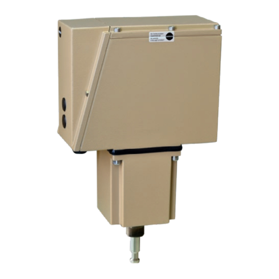
- Page 1 Electrohydraulic Actuator Type 3274 Fig. 1 ⋅ Type 3274 Mounting and Operating Instructions EB 8340 EN Edition June 2001...
- Page 2 Contents EB 8340 EN...
- Page 3 Safety instructions Assembly, start-up and operation of the device may only be performed by trained and experienced personnel familiar with this product. According to these mounting and operating instructions, trained personnel refers to individuals who are able to judge the work they are assigned to and recognize possible hazards due to their specialized training, their knowledge and experience as well as their knowledge of the applicable standards.
- Page 4 Technical data ± Ω Ω) ≤ Ω ≤ Ω Ω Ω, Ω Ω Ω EB 8340 EN...
- Page 5 Design and principle of operation ⋅ ⋅ ⋅ ⋅ ⋅ ⋅ ⋅ ⋅ ⋅ ⋅ ⋅ EB 8340 EN...
- Page 6 Design and principle of operation Ω EB 8340 EN...
- Page 7 Design and principle of operation Fig. 2 ⋅ Functional diagram EB 8340 EN...
-
Page 8: Installation
Installation Fig. 3 ⋅ Mounting position EB 8340 EN... - Page 9 Installation Fig. 4 ⋅ Actuator attachment EB 8340 EN...
- Page 10 Electrical connections Upon installation of the electric wir- ing, you are required to observe the regulations governing electrical power plant installation according to DIN VDE 0100 as well as the regulations of your power supplier. WARNING! Only connect to mains when the power is switched off.
- Page 11 Electrical connections "e" "a" ϑ eL a43 e53 1.311.321.33 2.312.32 2.33 Fig. 5 ⋅ Circuit diagram for actuators with three-point stepping signal ϑ "e" "a" 12 11 13 32 31 33 2.312.32 2.33 eL a43 e53 82 83 (0)4...20 mA (0)4...20 mA (0)2...10V (0)2...10V Fig.
- Page 12 Operation "e" "a" ϑ 12 11 13 32 31 33 2.312.32 2.33 eL a43 e53 82 83 (0)4...20 mA (0)2...10V Fig. 7 ⋅ Circuit diagram for actuators with position transmitter If, e.g. upon start-up of the plant, the control signal is to be interrupted and the control valve is to remain in a cer- tain position, the must...
- Page 13 Operation Fig. 8 ⋅ Terminal box with adjusting knobs EB 8340 EN...
- Page 14 Adjusting additional electric equipment • • • • • • • • • • • • • • • • • • • • • • • • • • • • • • 100% • • • • • <...
- Page 15 Adjusting additional electric equipment Note for split-range mode: To prevent the valves from overlapping when they are being adjusted, a dead band as shown in Fig. 9, for example, ±0.5 mA should be taken into account. Valve 1 would then be set from 11.5 to 4 mA and Valve 2 from 12.5 to 20 mA, the corre- sponding values also apply for V input sig- nals.
- Page 16 Adjusting additional electric equipment Ω Fig. 11 ⋅ Travel adjustment EB 8340 EN...
- Page 17 Adjusting additional electric equipment Note: The positioner can also be used as a "mere position transmitter". To proceed, remove the wires that lead from the positioner case to the terminals aL and eL and strip the insulation off the free wire ends.
- Page 18 Adjusting additional electric equipment EB 8340 EN...
- Page 19 Dimensions in mm Fig. 12 ⋅ Electric (left) and inductive (right) limit switches EB 8340 EN...
- Page 20 ⋅ ⋅ ⋅ ⋅...
Need help?
Do you have a question about the 3274 and is the answer not in the manual?
Questions and answers