Samson 3271-5 Mounting And Operating Instructions
Pneumatic actuators
Hide thumbs
Also See for 3271-5:
- Mounting and operating instructions (52 pages) ,
- Mounting and operating instructions (70 pages) ,
- Mounting and operating instructions (48 pages)

Subscribe to Our Youtube Channel
Related Manuals for Samson 3271-5


Summary of Contents for Samson 3271-5
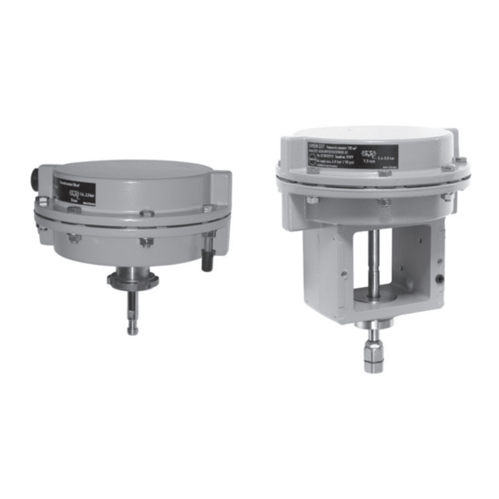
- Page 1 EB 8310-1 EN Translation of original instructions Type 3271 Pneumatic Actuator Type 3277 Pneumatic Actuator Type 3271-5 and Type 3277-5 Pneumatic Actuators (120 cm²) Edition October 2019...
- Page 2 Note on these mounting and operating instructions These mounting and operating instructions assist you in mounting and operating the device safely. The instructions are binding for handling SAMSON devices. The images shown in these instructions are for illustration purposes only. The actual product may vary.
-
Page 3: Table Of Contents
Contents Safety instructions and measures ..............1-1 Notes on possible severe personal injury ............1-3 Notes on possible personal injury ..............1-4 Notes on possible property damage .............1-5 Markings on the device ................2-1 Actuator nameplate ..................2-1 Label indicating actuator with preloaded springs ...........2-2 Design and principle of operation ...............3-1 Direction of action and signal pressure routing ..........3-3 Fail-safe action ...................3-3... - Page 4 Removal ....................11-1 11.1 Removing the actuator from the valve ............11-2 11.2 Relieving the spring compression in the actuator ..........11-4 Repairs ....................12-1 12.1 Returning devices to SAMSON ..............12-1 Disposal ....................13-1 Certificates ....................14-1 Annex......................15-1 15.1 Tightening torques, lubricants and tools ............15-1 15.2 Spare parts ....................15-1...
-
Page 5: Safety Instructions And Measures
Therefore, operators must ensure that the actuator is only used in operating conditions that meet the specifications used for sizing the actuator at the ordering stage. In case operators intend to use the actuator in other applications or conditions than specified, contact SAMSON. SAMSON does not assume any liability for damage resulting from the failure to use the de- vice for its intended purpose or for damage caused by external forces or any other external factors. Î Refer to the technical data and nameplate for limits and fields of application as well as possible uses. - Page 6 − Eye protection and hearing protection while the actuator is operating. Î Check with the plant operator for details on further protective equipment. Revisions and other modifications Revisions, conversions or other modifications of the product are not authorized by SAMSON. They are performed at the user's own risk and may lead to safety hazards, for example. Fur- thermore, the product may no longer meet the requirements for its intended use.
-
Page 7: Notes On Possible Severe Personal Injury
Safety instructions and measures Referenced standards and regulations According to the ignition risk assessment performed in accordance with EN 13463-1:2009, section 5.2, the non-electrical actuators do not have their own potential ignition source even in the rare incident of an operating fault. As a result, they do not fall within the scope of Di- rective 2014/34/EU. -
Page 8: Notes On Possible Personal Injury
Safety instructions and measures 1.2 Notes on possible personal injury WARNING Crush hazard arising from moving parts. The actuator contains moving parts (actuator stem), which can injure hands or fingers if inserted into the actuator. Î Do not touch the actuator stem or insert hands or finger into the yoke or beneath the actuator stem while the air supply is connected to the actuator. Î While working on the actuator, disconnect and lock the pneumatic air supply as well as the control signal. -
Page 9: Notes On Possible Property Damage
Risk of actuator damage due to the use of unsuitable tools. Certain tools are required to work on the actuator. Î Only use tools approved by SAMSON (u AB 0100). Risk of actuator damage due to the use of unsuitable lubricants. The lubricants to be used depend on the actuator material. Unsuitable lubricants may corrode and damage the surface. - Page 10 EB 8310-1 EN...
-
Page 11: Markings On The Device
16 Date of manufacture 17 Data Matrix code SAMSON Pneumatic actuator See technical data for ambient temperature Model Var.-ID Serial no. 11/ 12 Air supply max. SAMSON AG D-60314 Frankfurt Made in Germany Fig. 2-1: Nameplate of Type 3271 Actuator EB 8310-1 EN... -
Page 12: Label Indicating Actuator With Preloaded Springs
Markings on the device 2.2 Label indicating actuator with preloaded springs A label on the actuator indicates that the ac- tuator springs are preloaded in the delivered state (see Fig. 2-2). ACHTUNG ! ATTENTION ! ATTENTION ! VORGESPANNTER PRE-LOADED SERVO-MOTEUR ANTRIEB ACTUATOR PRECONTRAINT Fig. 2-2: Adhesive label indicating preloaded actuator springs in the delivered state EB 8310-1 EN... -
Page 13: Design And Principle Of Operation
. The direction of ac- tion of the actuator stem (A7) depends on how the springs are installed in the actuator. Several springs may be fitted into one anoth- A15 A9 A20/21 A5.1 A5.2 A133 A26/27 Fig. 3-1: Type 3271-5 Actuator with 120 cm² actuator area EB 8310-1 EN... - Page 14 Design and principle of operation A20/21 A133 A5.2 A5.1 A2.1 A2.1 A27.3 A27.1 A26/27 Version for micro-flow valve Fig. 3-2: Type 3277-5 Actuator with 120 cm² actuator area Legend for Fig. 3-1 and Fig. 3-2 Top diaphragm case A5.1 Diaphragm plate A26/27Stem connector clamps Bottom diaphragm case A5.2 Diaphragm plate A27.1 Stem connector nut A2.1...
-
Page 15: Direction Of Action And Signal Pressure Routing
3.1 Direction of action and Reversal of the direction of action signal pressure routing The direction of action for both Type 3271 and Type 3277 can be reversed (see the Type 3271-5 (see Fig. 3-1) 'Service and conversion work' section). In the "actuator stem extends" version, the 3.2 Fail-safe action signal pressure is routed through the bottom... -
Page 16: Version With Direction Of Action "Actuator Stem Retracts
Design and principle of operation Switchover plate Connecting plate A2.7 A2.9 A2.8 A2.4 A2.6 A2.4 A2.5 A2.5 Actuator stem extends Actuator stem retracts Actuator stem Left Right Left Right extends retracts attachment attachment attachment attachment A2.4 Symbol A2.7 With right attachment A2.5 Marking for signal pressure input A2.8... -
Page 17: Versions
Further- more, the vent plugs allow air intake to pre- − Standard version vent a vacuum from forming in the device. The housings of Type 3271-5 and u AB 07 Type 3277-5 Pneumatic Actuators have an actuator area of 120 cm² and are Lifting fixture made of die-cast aluminum. - Page 18 –35 to +80 °C –31 to +176 °F Dimensions and weights On/off service: –20 to +80 °C See Table 3-1 and dimensional drawings on –4 to +176 °F page 3-7 and 3-8. Table 3-1: Dimensions in mm and weights in kg Actuator Type 3271-5 3277-5 Actuator area cm² rated Height – ØD Diameter ØD2 Thread Ød...
- Page 19 Design and principle of operation Dimensional drawings ØD ØD ØD2 Ød ØD2 Type 3271-5 Type 3277-5 Ød EB 8310-1 EN...
- Page 20 Design and principle of operation Dimensional drawings ØD ØD ØD2 ØD2 Ød Ød Type 3271-5 with handwheel Type 3277-5 with travel stop ØD2 ØD2 M14 x 1 M14 x 1 Ød Ød Versions with 7.5 mm travel for Type 3510 Micro-flow Valve EB 8310-1 EN...
-
Page 21: Shipment And On-Site Transport
Risk of lifting equipment tipping over and damage. Report any damage to risk of damage to lifting accessories due to SAMSON and the forwarding agent exceeding the rated lifting capacity. (refer to delivery note). Î Only use approved lifting equipment and 3. -
Page 22: Transporting The Actuator
Î Observe the storage instructions. tainer or on the pallet to transport it. Î Avoid long storage times. Î Observe the transport instructions. Î Contact SAMSON in case of different storage conditions or long storage peri- Transport instructions ods. − Protect the actuator against external in- fluences (e.g. impact). - Page 23 Shipment and on-site transport − Make sure that the ambient air is free of acids or other corrosive media. − The permissible storage temperature is between –20 and +65 °C. − Do not place any objects on the actuator. Special storage instructions for elastomers Elastomer, e.g.
- Page 24 EB 8310-1 EN...
-
Page 25: Mounting And Assembly
5.2 Mounting the device it has become blocked (e.g. due to seiz- ing up after remaining in the same posi- Depending on the version, SAMSON control tion for a long time), release any stored valves are either delivered with the actuator energy in the actuator (e.g. -
Page 26: Mounting The Actuator Onto The Valve
Risk of actuator damage due to the use of 6. Place the actuator onto the valve bonnet unsuitable tools. (2) and secure it with the ring nut. Î Only use tools approved by SAMSON (u AB 0100). 7. Connect the signal pressure. See sec- tion 5.2.2. - Page 27 Mounting and assembly 2. Loosely thread the lock nut (A27.3) and tor stem (A7) to the bearing sleeve stem connector nut (A27.1) upward on (A27.2) on the plug stem (5). Disconnect the actuator. the signal pressure. 3. Place the actuator on the yoke (3). In the "actuator stem retracts"...
- Page 28 Mounting and assembly Yoke Plug stem with plug Travel indicator scale Bottom diaphragm case Actuator stem Ring nut A27.1 Stem connector nut A27.2 Bearing sleeve (bottom part of the stem connector) A27.3 Lock nut Fig. 5-2: Type 3277 Pneumatic A27.3 Actuator on a A27.1 Type 3510 Micro-flow A27.2...
-
Page 29: Connecting The Air Supply
'Start-up' sec- tion). Note If necessary, repeat the action described in 7 a) Type 3271-5 until the stem connector is correctly adjusted. 8. Lock the position of the stem connector Version with fail-safe action "actuator stem extends"... - Page 30 Mounting and assembly b) Type 3277-5 tion with the marking (A2.5). See Fig. 5-4. Operation with positioner (switchover Î Make sure that the gasket for the con- plate) necting plate is correctly inserted. Î Turn the switchover plate to align the Î The connecting plate has threaded holes symbol (A2.4) matching the fail-safe ac- with NPT and G threads.
-
Page 31: Start-Up
Start-up 6 Start-up WARNING WARNING The work described in this section is only to Risk of personal injury due to exhaust air be performed by personnel qualified for the being vented. assignment accordingly. The actuator is operated with air. As a result, air is vented during operation. Î... -
Page 32: Adapting The Travel Range
Version with direction of action "actuator ple, to the configuration ID or the symbol af- stem extends" ter reversal of the direction of action. When a SAMSON valve is combined with Î Immediately renew any nameplates or an oversized actuator (i.e. the rated actuator labels with incorrect or outdated infor- travel is larger than rated valve travel), the mation. -
Page 33: Travel Stop
Start-up 6.2 Travel stop 4. Attach the cover (A73) and retighten the lock nut (A70). In the version with travel stop, the maximum and minimum actuator travel can be limited 6.2.2 Top travel stop (maximum (see Fig. 6-1). travel) 6.2.1 Bottom travel stop 1. -
Page 34: Extending The Actuator Stem Manually
1. Turn the handwheel counterclockwise until the top stop position is reached. 2. Retract the actuator stem up to the re- quired position. Stem connector Horizontal mark- ing on the housing Handwheel Fig. 6-2: Type 3271-5 Actuator with handwheel EB 8310-1 EN... -
Page 35: Operation
Î Wear eye and hearing protection when labels with incorrect or outdated infor- working near the actuator. mation. Î Add any new values to the nameplate. If necessary, contact SAMSON to obtain a WARNING WARNING new nameplate. Crush hazard arising from the moving actu- ator stem. -
Page 36: Manual Mode (Versions With Handwheel Only)
Operation 7.4 Additional notes con- Version with direction of action "actuator stem retracts" cerning operation With fail-safe action "actuator stem retracts Î Label actuators with reduced supply (FE)", the permissible supply pressure must pressure with a sticker ("Max. supply not exceed the upper bench range value by pressure limited to ... -
Page 37: Malfunctions
Malfunctions 8 Malfunctions 8.1 Troubleshooting Malfunction Possible reasons Recommended action Actuator stem does not Actuator is blocked. Check attachment. move on demand. Unblock the actuator. WARNING! A blocked actuator (e.g. due to seizing up after remaining in the same position for a long time) can suddenly start to move uncontrollably. Injury to hands or fingers is possible if they are inserted into the actuator or valve. -
Page 38: Emergency Action
Malfunctions 8.2 Emergency action The plant operator is responsible for emer- gency action to be taken in the plant. EB 8310-1 EN... -
Page 39: Service And Conversion Work
Service and conversion work 9 Service and conversion work WARNING WARNING The work described in this section is only to Risk of personal injury due to exhaust air be performed by personnel qualified for the being vented. assignment accordingly. The actuator is operated with air. As a result, air is vented during operation. -
Page 40: Periodic Testing
NOTICE Risk of actuator damage due to the use of unsuitable tools. 9.2 Preparation for servicing Î Only use tools approved by SAMSON or conversion work (u AB 0100). 1. Lay out the necessary material and tools to have them ready for the intended NOTICE work. -
Page 41: Mounting The Actuator On The Valve After Servicing Or Conversion Work
Service and conversion work 9.4 Service work Note To remove an actuator with "stem extends" See Fig. 9-1 fail-safe action and/or with preloaded 9.4.1 Replacing the dia- springs, a certain signal pressure must be applied to the actuator (see the 'Removal' phragm section). - Page 42 Service and conversion work A15 A9 Fig. 9-1: Type 3271-5 and Type 3277-5 Pneumatic Actuators A5.1 A5.2 Type 3271-5 A20/21 A2.1 Type 3277-5 A133 Top diaphragm case Actuator stem Hex nut Bottom diaphragm case Ring nut Radial shaft seal A2.1 Switchover/connecting Hex nut Wiper ring plate for signal pressure...
- Page 43 Service and conversion work 5. Place the new diaphragm on the dia- NOTICE phragm plate (A5.2). Place on the other Malfunction due to loosened nut. diaphragm plate (A5.1). The nut (A9) on the actuator stem serves to 6. Check the sealing element of the collar adjust the dimension a.
-
Page 44: Replacing The Actuator Stem Seals
Service and conversion work 9.4.2 Replacing the actuator (A5.2) in the bottom diaphragm case (A2). stem seals 10. Place the springs (A10) into the bottom diaphragm case, centering them in the intended recesses. We recommend to also replace the actuator 11. -
Page 45: Conversion Work
Service and conversion work a) Reversal of the direction of (A5.2) in the bottom diaphragm case (A2). action from stem extends to 10. Place on the top diaphragm case (A1). stem retracts 11. Fasten the top and bottom diaphragm cases (A1, A2) together using the nuts 1. - Page 46 (A21) and bolts (A20). Observe tighten- 4. Unscrew the collar nut (A15). ing torques. NOTICE 11. Type 3271-5: connect the signal pres- sure as described in 'Connecting the air Malfunction due to loosened nut. supply' in the 'Mounting and assembly' The nut (A9) on the actuator stem serves to section.
-
Page 47: Determining Dimension A
Service and conversion work 9.6 Determining dimension a 12. Type 3271-5: connect the signal pres- sure as described in 'Connecting the air If the nut (A9) has come undone at the actu- supply' in the 'Mounting and assembly' ator stem (A7) during service and conversion section. -
Page 48: Ordering Spare Parts And Operating Supplies
Service and conversion work 9.7 Ordering spare parts and operating supplies Contact your nearest SAMSON subsidiary or SAMSON's after-sales service for infor- mation on spare parts, lubricants and tools. Spare parts See the Annex for details on spare parts. Lubricant Details on suitable lubricants can be found in the document u AB 0100. -
Page 49: Decommissioning
Decommissioning 10 Decommissioning WARNING WARNING The work described in this section is only to Risk of personal injury due to exhaust air be performed by personnel qualified for the being vented. assignment accordingly. The actuator is operated with air. As a result, air is vented during operation. Î... - Page 50 10-2 EB 8310-1 EN...
-
Page 51: Removal
Removal 11 Removal WARNING WARNING The work described in this section is only to Risk of personal injury due to exhaust air be performed by personnel qualified for the being vented. assignment accordingly. The actuator is operated with air. As a result, air is vented during operation. Î... -
Page 52: Removing The Actuator From The Valve
Removal 11.1 Removing the actuator In the "actuator stem retracts" version: undo ring nut (A8). from the valve 4. Lift the actuator off the valve. a) Series 240 Valves 5. Fasten the lock nut (10) and stem con- nector nut (9) on the valve. 1. - Page 53 Removal b) Type 3510 Micro-flow Valve nector nut (A27.1) and bearing sleeve (A27.2) stationary and unscrew them. 1. Loosen the lock nut (A27.3). 3. Loosen the ring nut (A8). 2. In the "actuator stem extends" version: 4. Lift the actuator off the valve. to retract the actuator stem, apply a sig- 5.
-
Page 54: Relieving The Spring Compression In The Actuator
Removal 11.2 Relieving the spring com- pression in the actuator The long clamping bolts with long clamping nuts and the short bolts with short nuts are arranged evenly around the circumference of the actuator housing to fasten the top and bottom diaphragm cases together. -
Page 55: Repairs
Further information on returned devices and Î Contact SAMSON's after-sales service how they are handled can be found at for repair work. u www.samson.de > Service & Support > After Sales Service. 12.1 Returning devices to SAMSON Defective devices can be returned to SAMSON for repair. - Page 56 12-2 EB 8310-1 EN...
-
Page 57: Disposal
Disposal 13 Disposal Î Observe local, national and internation- al refuse regulations. Î Do not dispose of components, lubricants and hazardous substances together with your household waste. EB 8310-1 EN 13-1... - Page 58 13-2 EB 8310-1 EN...
-
Page 59: Certificates
Certificates 14 Certificates The declaration of incorporation in compli- ance with Machinery Directive 2006/42/EC for Type 3271-5 and Type 3277-5 Pneumat- ic Actuators with 120 cm² actuator area is provided on the next page. EB 8310-1 EN 14-1... - Page 60 14-2 EB 8310-1 EN...
-
Page 61: Annex
Annex 15 Annex 15.1 Tightening torques, lubri- cants and tools u AB 0100 for tools, tightening torques and lubricants 15.2 Spare parts Top diaphragm case Washer Bottom diaphragm case 26/27 Stem connector clamps Switchover or connecting plate 27.1 Stem connector nut 1) 2) Diaphragm 27.3 Lock nut Diaphragm plate Radial shaft seal Diaphragm plate... - Page 62 26/27 Stem extends (FA) Stem retracts (FE) Stem extends (FA) Stem retracts (FE) 26/27 Type 3271-5 and Type 3277-5 Actuators, 120 cm² 15-2 EB 8310-1 EN...
- Page 63 27.3 27.1 Stem extends (FA) Stem retracts (FE) Stem extends (FA) Stem retracts (FE) 27.3 27.1 Type 3271-5 and Type 3277-5 Actuator, 120 cm², as version for micro-flow valve EB 8310-1 EN 15-3...
-
Page 64: After-Sales Service
E-mail address You can reach our after-sales service at af- tersalesservice@samson.de. Addresses of SAMSON AG and its subsid- iaries The addresses of SAMSON, its subsidiaries, representatives and service facilities world- wide can be found on our website (www. - Page 66 EB 8310-1 EN SAMSON AKTIENGESELLSCHAFT Weismüllerstraße 3 · 60314 Frankfurt am Main, Germany Phone: +49 69 4009-0 · Fax: +49 69 4009-1507 samson@samson.de · www.samson.de...
Need help?
Do you have a question about the 3271-5 and is the answer not in the manual?
Questions and answers